


Stripes
The grid determines the size and distribution of the elements over the support.
Style curves define the stripes on the optical surface.
The shape of the stripes, their number and repartition over the support depend on the style curves selected for definition.
Axis System
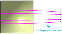
The grid axis system is used to define the way that the style curves are projected onto the support.
The axis system origin is optional. It is, by default, inherited from the support.
- Start angle/End angle.
- Flutes' concavity/convexity.
 |
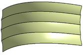 |
| Support and Style Curves viewed from the plane normal to Projection Direction. | Result of the feature when stripes are generated on the support according to style curves definition. |
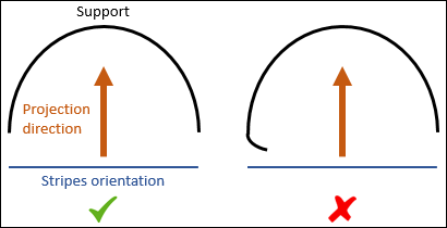
To ensure a correct construction when using a curved support, make sure the support does not close in on itself (see figure below). Otherwise, the stripes will not be projected correctly.
Definition
Styles curves are selected to demarcate the stripes.
These curves can be lines, splines or sketches. The stripes are oriented along X Grid, which is given by the tangent to the set of curves.
One incomplete style curve is enough to provoke a null result for the whole feature. To avoid construction issues, always use support surfaces larger than style curves.