
Mesh Fusion/Assembly
In HFSS 3D Layout, a hierarchical design is defined by the top-level layout and a collection of component instances. Component instances can be of different types, most commonly other components or 3D Components (MCAD). For mesh assembly/fusion (Mesh Fusion), this hierarchy is used to define independent mesh domains, with then ntop-level layout referred to as the “native” region. In allowing separate regions to be meshed independently, Mesh Fusion enables robust and rapid initial meshing.
To use Mesh Fusion, the native region must encapsulate all component instances. For a component instance to be modeled as a separate mesh domain, check the Mesh Fusion [Beta] box in the Access the Mesh Settings Window window.
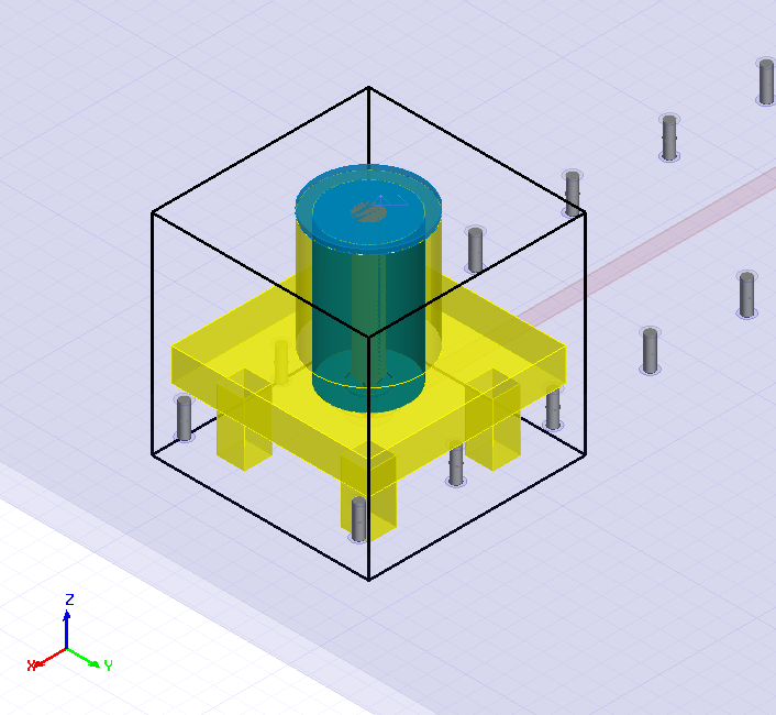
By default, component selected for Mesh Fusion are assigned a bounding-box envelope for its mesh region. If a 3D component has explicitly defined “mesh regions”, those is also available for envelope assignment.
Care should be taken when defining the domain envelopes to ensure:
- There is no overlap between native and component geometry.
- There is no overlap between component envelopes.
- Envelope definitions contain only planar faces.
- Envelope boundaries are not coincident with ports.
- Envelope definitions provide for optimal initial meshing.
- Insulate geometry not compatible with the Phi mesher from geometry that is compatible.
- Mesh geometry of different scales in their own domain.
Mesh Method Override
The initial mesh method for a given component instance can be selected in the Mesh Settings window. This allows for the optimal mesh technology to be applied on a component-by-component basis.

Access the Mesh Settings Window
To access the Mesh Settings window, complete these steps.
-
From the Layout Editor, select a 3D object in the active design to make its parameters appear in the Properties window.

-
If appropriate, click on the Param Values tab in the Properties window.
Mesh Fusion is supported only for layout and 3D components. If a component does not meet this requirement for Mesh Fusion, the option is not available on the Param Values tab.
-
Click the HFSS Mesher Settings [...] button to open the Mesh Settings window with Domain, Curved Surface, and Advanced tabs.
Some of the features of Mesh Fusion include:
- Systems with large variation in length scales can be successfully meshed (e.g., in the case of an IC mounted on a package, mesh the components separately and with optimal pre-processing for their respective scale).
- Different meshers can be selected for each component via the Initial Mesh Method area (i.e., choose between Auto, Phi or Phi Plus for an ECAD component, or Classic for an MCAD component).