
Using Layout Custom CS for Placement in HFSS 3D
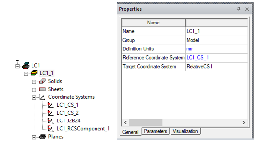
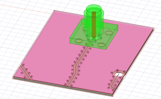
The ability to define coordinate systems in layout facilitates placing a layout component on a desired location relative to other geometry. In this example illustrates a 3D component (shown in green) that comes with a CS called “RelativeCS1”. This CS is located at the bottom of the component and at the center of the internal cylinder structure.
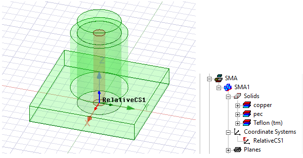
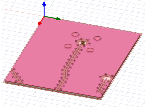
We also have a layout component shown in red. In the original layout design of this component, the global CS is located at one of the centers of the entire structure. Without this feature, when you create such a layout component in HFSS, its global CS will be used as the reference CS.
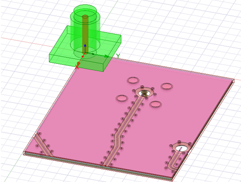
In this example, you want to place the layout component under the 3D component so that its holes (in the middle of the component) are aligned with the hole from the 3D component. However, there is no easy way to do that without preparing an appropriate custom coordinate system. You cannot just change the layout component’s target CS to “RelativeCS1” because that snaps the layout component’s global CS to the target CS, which will look like the figure below.
Without a custom CS, the only way you can do this is to manually move the layout component to the right place. Because the layout component does not have actual geometry for its holes, you cannot just move the layout component and snap its holes to the hole from the 3D component. You have to move it using a carefully measured distance, which you would acquire by going back to the original layout design to get the distance from the center of the hole to the global CS. Obviously, that workflow is tedious and error prone.
With this custom CS feature, the workflow in the original layout design, you create a new CS “CS_1” at the center of the holes if there is not one already. When you import the layout component, select this new CS as the reference CS.
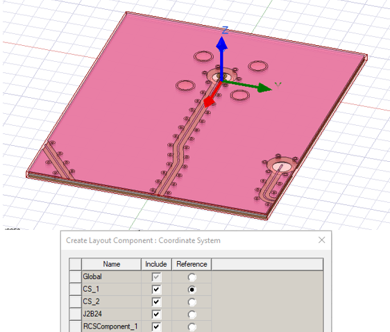
Using this new reference CS, the select the target CS as “RelativeCS1”.
If you use this approach the layout component moves to the right place where its reference CS “CS_1” snaps to the target CS “RelativeCS1”.
This workflow works well in a design having multiple layout components and 3D components, as you can now place component B relative to component A, component C relative component B, component D relative to component C, and so forth.
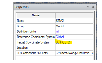
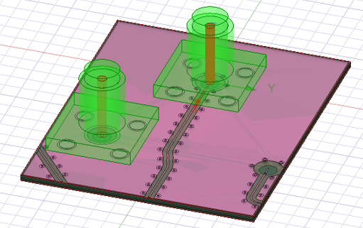
Continuing with the example, let’s suppose that you want to mount another 3D component on top of the layout component. To do this, we create additional hole groups on the layout design and place a relative coordinate system CS_2. When creating the layout component, you can choose this coordinate system CS_2 to be included as well.
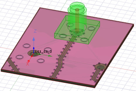
With this setup, it is easy to mount another 3D component on top of the layout component. You can just import the other 3D component and change its target CS to be CS_2, and the 3D component automatically snaps to the desired location.
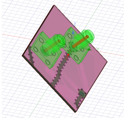
If you rotate the first 3D component, everything will be rotated along with it, based on the relative coordinate systems.
Related Topics
Using Layout Component in HFSS 3D Process Flow
Visualization for Layout Components in HFSS 3D
Visualization for RLC Boundaries and Component Groups Designated as Circuit Elements
Editing Layout Components in HFSS 3D
Using Layout Custom CS for Placement in HFSS 3D
Flex PCB Components in HFSS 3D
Field Plots on Layout Component's Layer or Net
Using the Fields Calculator with Layout Component in HFSS 3D