
Layout Component in HFSS 3D Process Flow
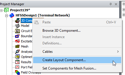
In the Project tree, right-click on the 3D Component icon, and select Create Layout Component... from the shortcut menu.
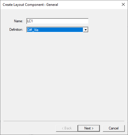
This opens the Create Layout Component dialog. If you have not made previous selections, only <undefined> is listed in the Definition field drop-down.
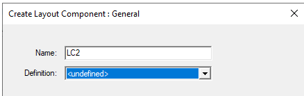
After you make selections, these will be listed.
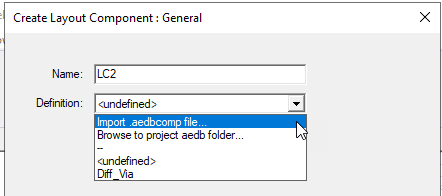
To begin, select Browse to project aedb folder..., or Import .aedbcomp file...
Selecting Browse to project aedb folder ... opens a browser window that allows you to select and import an aedb folder that contains the edb. Note: you need to browse into the aedb folder and click OK to import it.
Usually the *.aedb folder to import layout component should be a separate location that is independent of the target Ansys Electronics Desktop project file location. As the *.aedb is the location to store layout component data, this component may come from any where. If you attempt to import an encrypted component from the hierarchy of the current project, you will receive an error message. An encrypted component will not be in the first .aedb folder, but the one of the next two subfolders.
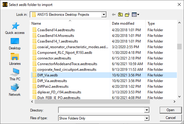
When you have made a valid selection, click Open to return to the Create Layout Component dialog.
Click Next to view the Variable Mapping page.
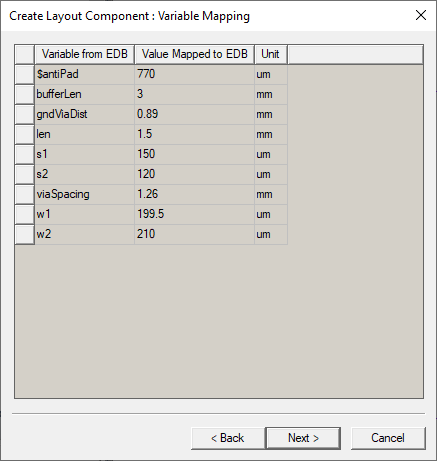
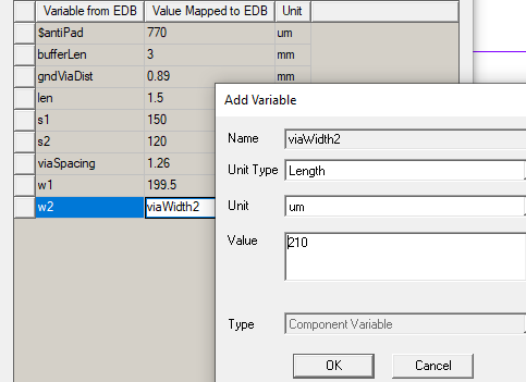
Here you can specify the component variable values, if you choose. You can map to design variables after creation and change the component variable through component property window.
After you edit values and add variables, click Next to view the Coordinate System page. If the original layout design includes custom coordinate systems, these will be displayed. If not, only the Global CS is shown.
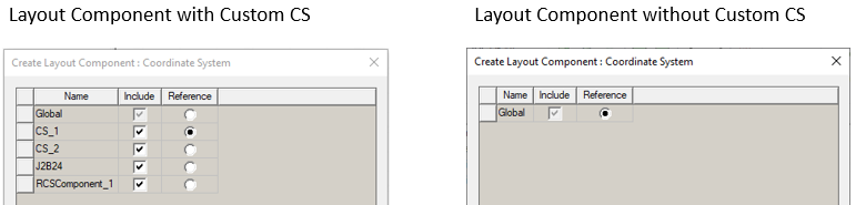
Because you can use custom coordinate systems defined in original Layout design to simplify placement in HFSS, you should consider creating them in Layout for this purpose. All coordinate systems of the selected component are extracted from the 3D Layout design and displayed in the page. The global CS is always displayed. You can select one or more CS in the “Include” column to import them to the HFSS design. The global CS and the CS that is selected as the reference CS are always included. Once a CS is selected in the “Include” column, each component instance of that definition will create such CS in its modeler tree, which is shown below.
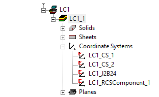
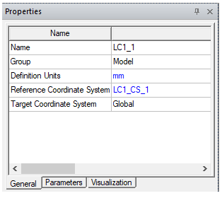
You can also select one CS from the table to be the reference CS by using the “Reference” column. By default, the CS closest to the center of the layout component is marked as the reference. Once the layout component creation/Editing is finished, the selected CS is displayed in the component’s general property window.
The Layout Component in HFSS 3D Process Flow section provides an example use of this feature.
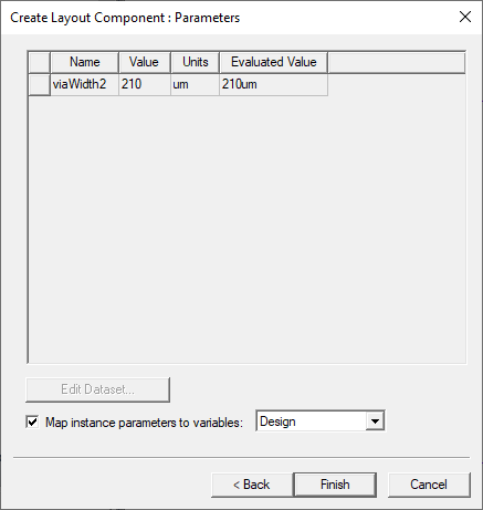
Click Next to view the Parameters page that shows variables you have added. You can then map instance parameters to Design or Project variables.
Click Finish. When you have added a Layout Component instance, it appears in the Project tree, the History Tree, and the Model window.
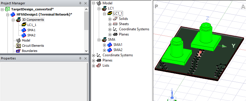
Selecting the component highlights it in the Model window, and displays its Properties window.
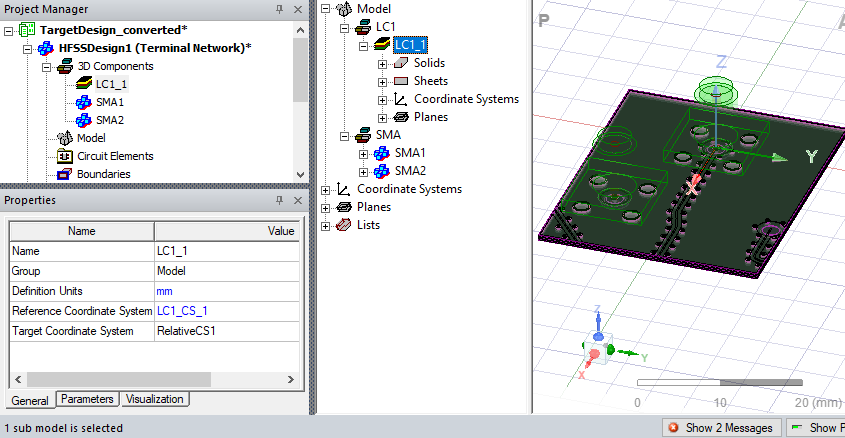
The Properties window includes General tab, Parameters tab where you can edit instance values for variables you have created, and Visualization.
Related Topics
Visualization for Layout Components in HFSS 3D
Visualization for RLC Boundaries and Component Groups Designated as Circuit Elements
Show Nets for Layout Components in HFSS 3D Geometries
Editing Layout Components in HFSS 3D