
Visualization for Layout Components in HFSS 3D Modeler
You can show each layout component in the 3D editor and specify the visualization attributes of each layer, net, or object in the layout component. This can be done in each layout component’s property window through the Visualization tab or by checking Show Layout in the right-click shortcut menu on the component. If Show Layout is not checked, the layout component is displayed as a bounding box. You can also visualize RLC boundaries assigned on an edge or across layers, and component groups that are categorized as circuit elements.
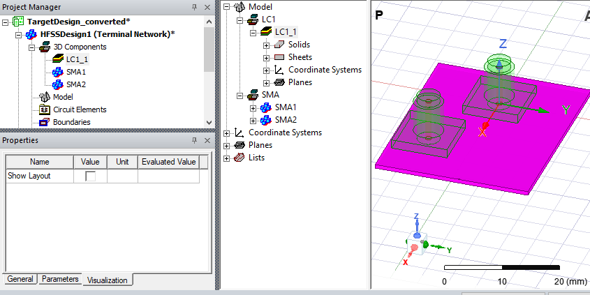
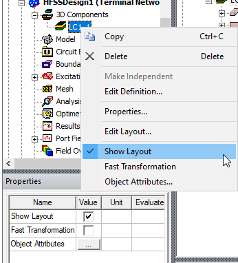
Using Show Layout for Layout Components
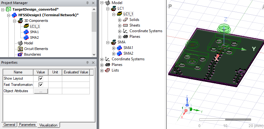
Checking Show Layout on the shortcut menu or the Visualization tab displays the layout.
Object Attributes Control of Visualization for Layout Components
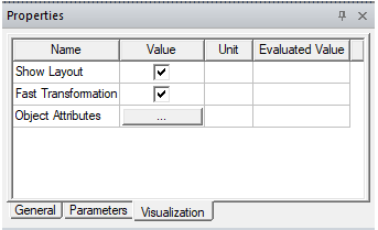
If Show Layout is checked, the Object Attributes [...] button provides access to the visualization attributes of the component in a separate dialog. The Fast Transformation option toggles whether layout components show outlines of objects across layers during view changes. This improves the visualization performance.
This is the Object Attributes dialog. It provides fine control over how the Layout 3D Component is displayed.
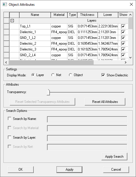
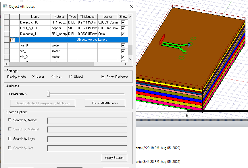
In the Settings group box, you can set the display mode as Layer, Net, or Object, and whether you want to Show Dielectric objects in the component. In the layer mode, this dialog displays information about each layer like the material, type, and thickness. Each layer is sorted by height instead of alphabetically. A button named Reset All Attributes is added to the dialog to quickly reset the attributes of all items in this mode. The Layer mode displays every layer and every other object across layers separated by a separator. For Layer mode only, the table includes grouping buttons.
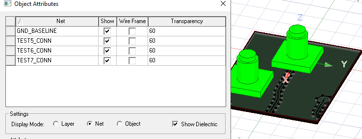
The Net mode displays component nets and ignore others objects not belonging to a net.
The Object mode displays every object from the component. Note: that for large layout components with many objects, the performance in object mode could be slow.
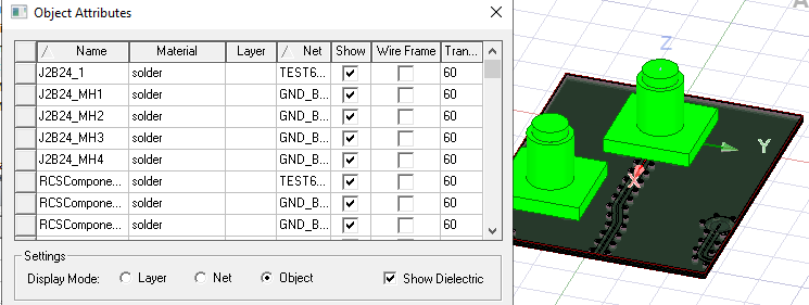
For each item listed in the table, you can choose how you want to show it by selecting options in the Show, Wire Frame, and Transparency columns. You can check/uncheck the entire Show or Wire Frame column by clicking the respective column header. Click the Transparency column header to select/deselect all rows. Click other column headers to sort the table according to names from that column.
The dialog supports multi-select functionality. When you select rows the buttons in the “Attributes” group box becomes available.
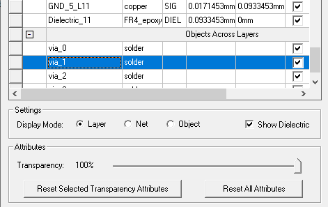
You can drag the Transparency slider bar to adjust the transparency value of all selected rows. Finally, the Reset Selected Transparency Attributes button sets the transparency value of all selected rows back to the default values when the component was imported. The default transparency of a layer or a net is calculated as the average transparency of all objects belonging to it.
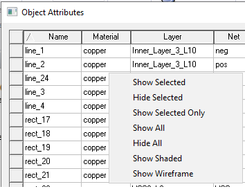
In the Layout Component Object Attributes dialog, if you right-click anywhere inside the table, a pop-up menu will appear to let you quickly turn on/off visualization of objects.
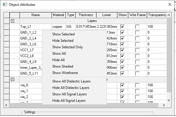
If the dialog’s display mode is layer mode, and you right-click the region containing layers, the pop-up menu contains additional menu items for quickly showing/hiding certain layers.
The dialog also has search functionality to search for specific items. You can enter their search criteria in the Search Options group box.
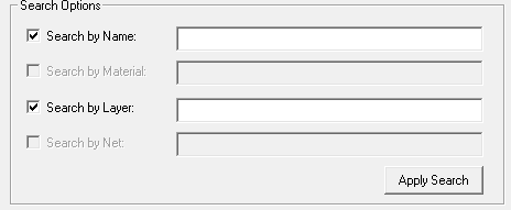
By clicking Apply Search, the table refreshes to only show items that match the search criteria.
Related Topics
Using Layout Component in HFSS 3D Process Flow
Visualization for RLC Boundaries and Component Groups Designated as Circuit Elements
Editing Layout Components in HFSS 3D
Using Layout Custom CS for Placement in HFSS 3D