Flex PCB Component Support in HFSS 3D
Users can now export Flex PCBs designs (i.e., components with rigid-flex bends) from HFSS 3D Layout as components and import them to HFSS 3D. All regular component functionality is supported for components with rigid-flex bends (e.g., visualization attributes, validation checks, component coordinate systems, circuit elements visualization, net identification, mesh fusion, post-processing, et cetera).
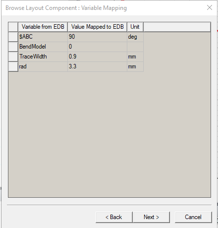
When components with rigid-flex bends are imported, the BendModel variable appears in the Browse Layout Component : Variable Mapping window, in addition to other variable types shared by other components in the definition design. When the value of BendModel is 0, all rigid-flex bends on the components are inactive. Otherwise, the bends on the components are active.
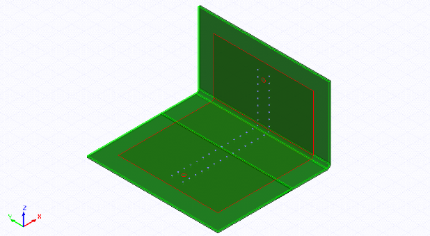
When rigid-flex bends are active, all ports, circuit elements, and component coordinate systems on the bent part of the components are transformed to accommodate the bends.
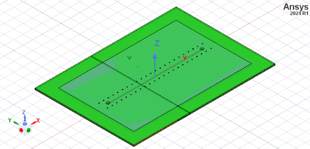
If bends are inactive (i.e., BendModel = 0), all bends in components are inactive, and the components appear in their unbent states.
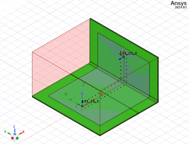
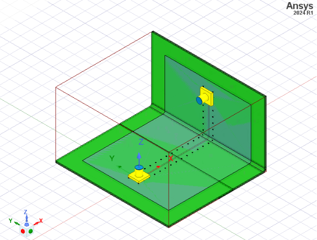
With bends re-enabled, other 3D components can be imported and assembled with bent components.
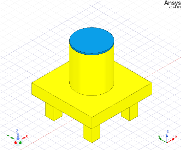
The final assembled system may match the following example (i.e., two 3D components placed on the two coordinate systems of the component).
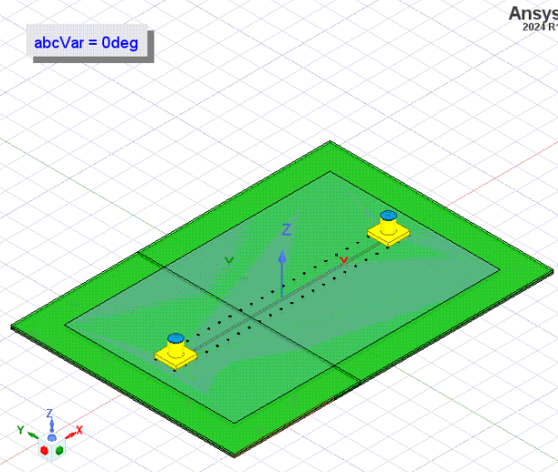
In the following example, the angle of the bend is parametrized with a variable. When components are imported to HFSS, the parametrized variable can be used to control their bends. If the value is changed, the bend angle of the components update to reflect the change. Other parts of the design that depend on the bend angle are also updated.

Users can also generate an animation based on the different values of the bend angle.

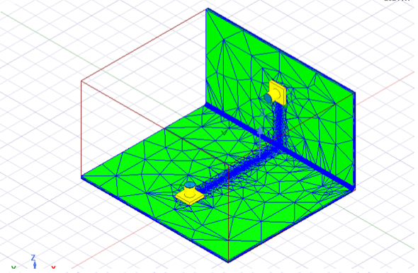
Components with rigid-flex bends can also be meshed and simulated. All the simulation and post-processing functionality for regular components are supported for components with rigid-flex bends and the workflows are identical; plot the mesh-selected nets and layers of the components, as appropriate.
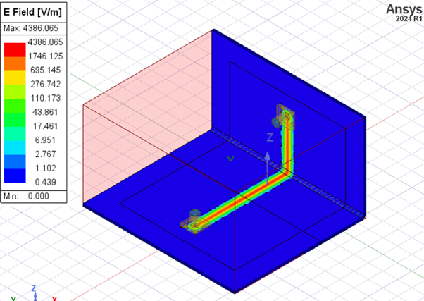
Or plot the fields-selected nets and layers of the of the component, as appropriate.
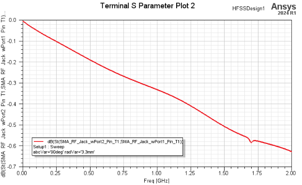
Finally, create plots (e.g. S Parameter plots).