
Visualization for RLC boundaries and Component Groups Categorized as Circuit Elements
You can visualize RLC elements for layout components in HFSS in the same way as they appear in HFSS 3D Layout Components
-
The types of circuit elements that can be visualized include RLC boundaries assigned on an edge or across layers, and component groups that are categorized as circuit elements. Other forms of circuit elements currently cannot be included in a layout component and thus are not supported.
-
Display each circuit element’s name on top of the visualization.
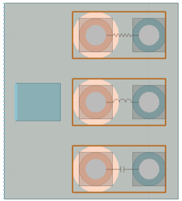
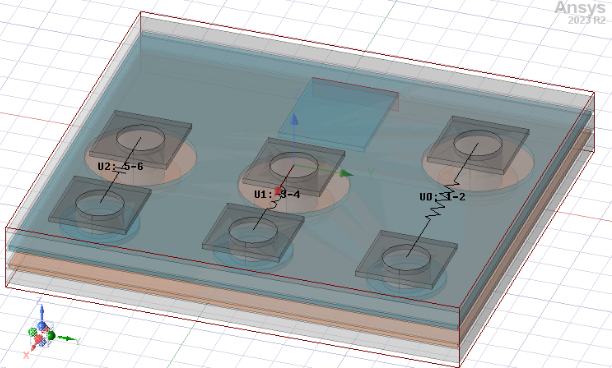
You can toggle these RLC visualizations with the Show Layout option. The intent is to display each layout component’s component data in its property window similar to that of 3D components. For example, given a 3D layout design with circuit elements, the visualization of circuit elements in the HFSS 3D Layout modeler window can appear as shown below.
When imported as a Layout Component into HFSS, the layout components would appear as shown below.
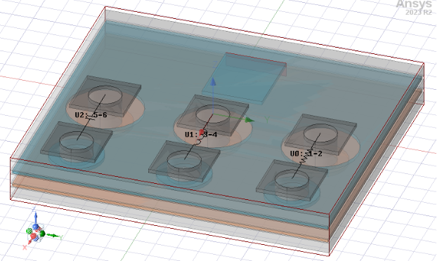
The names of the circuit elements are also displayed on top of the visualization. When the circuit elements become too small to display due to zooming out, these names disappear to improve the clarity of the window. This visualization of RLC circuits with their names can be turned on/off by toggling the layout component’s “Show Layout” option.
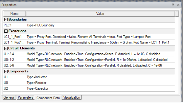
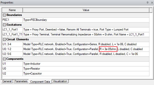
This property page will display the information about each boundary, excitation, circuit element, and component group of the layout component.
Parameter Support for Layout Components
The circuit element visualization and component data property page supports parametrization. If the location of a circuit element or a part of the description in the component data is controlled by a parameter, changing this parameter will cause the visualization or the property page to update and reflect the change.
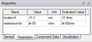
For example, in the above example, the layout component has 2 variables as shown below.
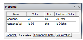
The variable locationX controls the x-location of one of the pins in circuit element U0: 1-2. The variable resistanceVal controls the electrical resistance in circuit element U0: 1-2. You could change the value of these two variables shown below.
With this variable change, the component’s circuit element visualization updates to reflect this change.
The Properties page for affected Circuit Elements also updates.
Related Topics
Using Layout Component in HFSS 3D Process Flow
Editing Layout Components in HFSS 3D
Using Layout Custom CS for Placement in HFSS 3D
Show Nets for Layout Components in HFSS 3D Geometries