


The procedure for setting up and solving fuel cell problems using the PEMFC model is described in detail in this section. Refer to the following sections for more information:
- 32.1.1. Overview and Limitations
- 32.1.2. Geometry Definition for the PEMFC Model
- 32.1.3. Installing the PEMFC Model
- 32.1.4. Loading the PEMFC Module
- 32.1.5. Workflow for Using the PEMFC Module
- 32.1.6. Setting Up the PEMFC Module
- 32.1.7. PEMFC Model Boundary Conditions
- 32.1.8. Solution Guidelines for the PEMFC Model
- 32.1.9. Postprocessing the PEMFC Model
- 32.1.10. User-Accessible Functions
The Ansys Fluent PEMFC model is composed of several user-defined functions (UDFs) and a graphical user interface. The potential fields are solved as user-defined scalars. The capillary pressure, the water content (water in dissolved phase), and liquid saturation in the gas channels are also solved as user-defined scalars. The electrochemical reactions occurring in the catalyst layers are modeled through various source terms while other model parameters are handled through the user interface. The PEMFC model can be used in parallel Ansys Fluent as well.
Note the following limitation when using the PEMFC model:
The anisotropic species diffusivity option is not compatible with the PEMFC model.
Due to the fact that there is a number of different physical zones associated with the fuel cell, the following regions must be present in the fuel cell mesh (see Figure 20.1: Schematic of a PEM Fuel Cell):
Anode flow channel
Anode gas diffusion layer
Anode micro-porous layer (optional)
Anode catalyst layer
Membrane layer (solid)
Cathode catalyst layer
Cathode micro-porous layer (optional)
Cathode gas diffusion layer
Cathode flow channel
The following zones have to be identified, if present in the fuel cell mesh:
Anode current collector (solid)
Cathode current collector (solid)
Coolant channel
The PEMFC model is provided as an add-on module with the standard Ansys Fluent licensed
software. The module is installed with the standard installation of Ansys Fluent in a
directory called addons/pemfc in your installation area.
The PEMFC module consists of a UDF library and a pre-compiled Scheme library, which
must be loaded and activated before calculations can be performed.
The PEMFC module can be loaded only after a valid Ansys Fluent case file has been set or read.
There are two different ways in which you can load the PEMFC module into Ansys Fluent:
Through the ribbon
In the Physics ribbon tab, click (Models group), and select PEM Fuel Cell Model....
 Physics →
Models → More
→ PEM Fuel Cell Model...
Physics →
Models → More
→ PEM Fuel Cell Model...Once the PEMFC module is loaded into Ansys Fluent, the PEM Fuel Cell Model dialog box opens where you can enable and set the PEMFC model as described in Setting Up the PEMFC Module.
Through the text user interface (TUI)
The module The text command to load the add-on module is
define→models→addon-moduleA list of Ansys Fluent add-on modules is displayed:
> /define/models/addon-module
Fluent  Addon Modules:
     0. None
     1. MHD Model
     2. Fiber Model
     3. Fuel Cell and Electrolysis Model
     4. SOFC Model with Unresolved Electrolyte
     5. Population Balance Model
     6. Adjoint Solver
     7. Single Potential Battery Module
     8. MSMD Battery Model
     9. PEM Fuel Cell Model
Enter Module Number: [0] 9
Select the PEM Fuel Cell Model by entering the module number
9.
During the loading process, a Scheme library (containing the graphical and text user interface) and a UDF library (containing a set of user defined functions) are loaded into Ansys Fluent.
The PEMFC model can be used to model polymer electrolyte membrane fuel cells (PEMFC). The following describes an overview of the procedure required in order to use the PEMFC model in Ansys Fluent.
Start Ansys Fluent.
You must start Ansys Fluent in 3D double-precision mode. Note that the PEMFC model is only available in 3D.
Read the case or mesh file.
Scale the mesh, if necessary.
Use the PEM Fuel Cell Model dialog box to define the fuel cell model parameters.
Define material properties.
Set the operating conditions.
Set the boundary conditions.
Start the calculations.
Save the case and data files.
Process your results.
Important:
The PEM Fuel Cell Model dialog box greatly simplifies the input of parameters and boundary conditions, but it does not replace the boundary conditions interface. Therefore, it is a good policy to start the setup with the PEM Fuel Cell Model dialog box and do the finishing steps for boundary conditions afterwards.
Note that the majority of this chapter describes how to set up the Ansys Fluent PEMFC model using the graphical user interface. You can also perform various tasks using the text user interface. For more information, see Using the PEMFC Text User Interface.
Once the module has been loaded, in order to set fuel cell model parameters and assign properties to the relevant regions in your fuel cell, you need to access the fuel cell graphical user interface (the PEM Fuel Cell Model dialog box).
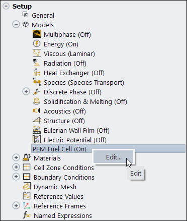
The PEM Fuel Cell Model dialog box can be accessed either through the ribbon (as described in Loading the PEMFC Module) or from the Setup/Models/PEM Fuel Cell tree item.
![]() Setup → Models
→ PEM Fuel Cell
Setup → Models
→ PEM Fuel Cell ![]() Edit...
Edit...
If the PEMFC model is not yet enabled, you can enable it by selecting Enable PEMFC in the PEM Fuel Cell Model dialog box.
Using the PEM Fuel Cell Model dialog box, you can identify the relevant zones for the current collectors, flow channels, gas diffusion layers, micro porous layers, catalyst layers, and the electrolyte (membrane). You can specify the following inputs using the PEM Fuel Cell Model dialog box. Optional inputs are indicated as such.
Set the appropriate options for the fuel cell model.
Set the various parameters for the fuel cell model.
Select the appropriate zones and specify the properties on the anode side.
Select the appropriate zones and specify the properties of the electrolyte/membrane.
Select the appropriate zones and specify the properties on the cathode side.
Provide input for advanced features such as contact resistivities, coolant channel properties, or stack management settings (optional).
Set solution controls such as under-relaxation factors (optional).
Provide input to assist reporting (optional).
Note: The default values of the fuel cell model parameters and zone properties are determined based on various data available in the literature (419, 476, 506, 586, 663 718, (listed in the Bibliography in the Fluent Theory Guide), and others).
Refer to the following sections for more information:
- 32.1.6.1. Specifying Model Options (Model Tab)
- 32.1.6.2. Specifying Model Parameters (Parameters Tab)
- 32.1.6.3. Specifying Anode Properties (Anode Tab)
- 32.1.6.4. Specifying Electrolyte/Membrane Properties (Electrolyte Tab)
- 32.1.6.5. Specifying Cathode Properties (Cathode Tab)
- 32.1.6.6. Setting the External Electrical Tabs (Electrical Tabs Tab)
- 32.1.6.7. Setting Advanced Properties (Advanced Tab)
- 32.1.6.8. Customizing the PEM Fuel Cell Module
- 32.1.6.9. Reporting on the Solution (Reports Tab)
- 32.1.6.10. User-Defined Functions Hooked to the PEMFC Module
The Model tab of the PEM Fuel Cell Model dialog box allows you to select or cancel the selection of various options when solving a fuel cell problem.
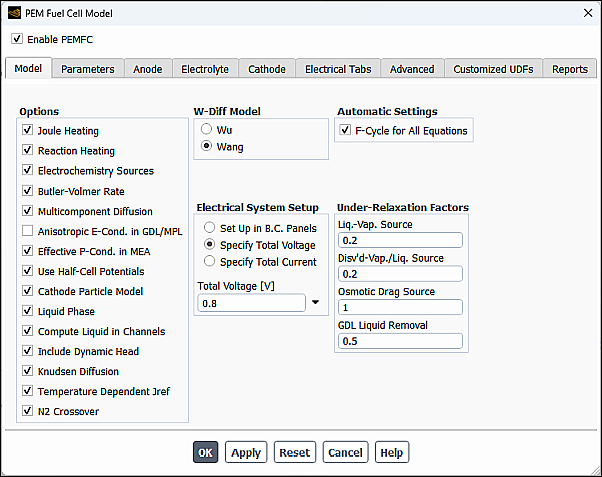
Options
Several fuel cell model options are available including:
- Joule Heating
takes into account ohmic heating. This option includes the
 terms in the energy source term in the
calculations. See Table 20.1: Volumetric Heat Source Terms for the list of
additional volumetric sources in the thermal energy equation.
terms in the energy source term in the
calculations. See Table 20.1: Volumetric Heat Source Terms for the list of
additional volumetric sources in the thermal energy equation.- Reaction Heating
takes into account the heat generated by the electrochemical reactions.
- Electrochemistry Sources
allows the PEMFC model to take electrochemistry effects into account. If you are only interested in the basic flow field throughout the fuel cell, you can turn off the Electrochemistry Sources option in order to suppress most effects of the PEMFC model. You may also turn off the effect of these sources in order to obtain a fluid flow initially, and then turn it back on.
- Butler-Volmer Rate
(the default) is used to compute the transfer currents inside the catalyst layers. If this option is turned off, the Tafel approximation (Equation 20–7 and Equation 20–8) is used.
- Liquid Phase
takes into account liquid phase calculations. Use this option if you are solving for liquid transport in the fuel cell.
- Multicomponent Diffusion
is used to compute the gas species mass diffusivity using the full multicomponent diffusion method as described in Equation 20–47, as opposed to the default option that uses Equation 20–45.
- Anisotropic E-cond. in GDL/MPL
is used to model the typically non-isotropic electrical conductivity. It is applicable only for porous electrodes (gas diffusion layers and micro porous layers).
Due to the fibrous structure of the porous material that is used for the electrodes (or gas diffusion layer), the electrical conductivity is typically non-isotropical, with the cross-plane components being orders of magnitude smaller than the in-plane components. This can be modeled using the Anisotropic E-cond in GDL/MPL setting. When this option is enabled, the Electrical Conductivity for the solid material used in the porous electrodes is no longer used. Instead, you need to specify, for this solid material, the electrical conductivity by choosing one of the three non-isotropical options for the UDS diffusivity (
UDS-0). The three options are: anisotropic; orthotropic; and cyl-orthotropic. For more information about these UDS Diffusivity options, refer to the Ansys Fluent User's Guide.For example, to use this feature, perform the following steps:
Select the Anisotropic E-cond in GDL/MPL option in the Model tab of the PEM Fuel Cell Model dialog box.
In the Create/Edit Materials dialog box, select
defined-per-udsfor UDS Diffusivity for the solid material that is to be used for the porous electrode.Select one of the three options for UDS-0: anisotropic; orthotropic; or cyl-orthotropic and set the appropriate values.
Important: Note that, in this case, the Electrical Conductivity for this solid material is ignored.
- Effective P-Cond. in MEA
enables the computation of the electrolyte phase conductivity
 with consideration of ionomer volume fraction and
tortuosity in the catalyst layers using Equation 20–48. If this option is disabled, then
with consideration of ionomer volume fraction and
tortuosity in the catalyst layers using Equation 20–48. If this option is disabled, then
 and
and  .
.- Use Half-Cell Potentials
enables the calculations of the anode and cathode half-cell potentials
 and
and  using the Nernst equations (Equation 20–13 and Equation 20–14). If this
option is disabled, the constant open-circuit voltage is assumed,
the
using the Nernst equations (Equation 20–13 and Equation 20–14). If this
option is disabled, the constant open-circuit voltage is assumed,
the  set to zero, and
  is set to a value specified for
V_Open in the
Parameters tab.
is set to a value specified for
V_Open in the
Parameters tab.- Cathode Particle Model
enables the cathode particle model. For information about this model, see The Cathode Particle Model.
- Liquid Phase
enables the liquid water transport equations in the computations. By default, this option is enabled.
- Compute Liquid in Channels
enables the solution of the liquid saturation equation in the gas channels, which helps in predicting the pressure drop increase. When this option is enabled, the viscous resistance in the gas channel is treated as a source term and is added directly to the momentum equations. By default, this option is disabled, and the equation is not solved.
- Include Dynamic Head
(if enabled) includes the dynamic pressure in the gas channel in Equation 20–35.
- Knudsen Diffusion
(if enabled) includes the effect of Knudsen diffusion in the calculation of the effective gas diffusivity using Equation 20–47 in the Fluent Theory Guide.
- Temperature Dependent Jref
(when enabled) takes into account the temperature dependency of the reference exchange current density (Equation 20–9 and Equation 20–10 in the Fluent Theory Guide). When this option is enabled (default), you can specify Activation Energy for J_ref and Reference Temperature for J_ref for the anode and cathode catalyst layers as further described.
- N2 Crossover
(when enabled) includes the effect of the N2 crossover flux across the membrane (Equation 20–10 in the Fluent Theory Guide). When this option is enabled, you must specify N2 Crossover factor in the Parameters tab (Other Parameters group box). This option is disabled by default.
- Ice Phase
(when enabled) includes the effect of the ice phase (Equation 20–41 in the Fluent Theory Guide). When this option is enabled, you must specify Desublimation Rate and Sublimation Rate in the Parameters tab (Other Parameters group box). This option is available only for transient simulations and disabled by default.
W-Diff Model
You can select one of the following formulations for the function
 in Equation 20–50:
- Wu
computes
 using Wu's formulation (Equation 20–51).
- Wang
computes
 using Wang's formulation (Equation 20–52).
Electrical System Setup
You can select one of the following methods to set up the electrical potential (UDS0) boundary conditions at external wall tabs:
- Set Up in B.C. Panels
When enabled, Ansys Fluent uses your electrical potential boundary conditions that you specified in the relevant boundary condition dialog boxes for the anode and cathode terminals. See PEMFC Model Boundary Conditions for more information.
- Specify Total Voltage
Allows you to specify Total Voltage, which is the cell or stack voltage (V). You have the option to specify the Total Voltage as a constant (default) or expression. See Creating and Using Expressions for more information about the expression specification method.
The electrical potential UDS0 conditions in the boundary condition dialog boxes are ignored. Ansys Fluent automatically sets the potential to zero at the anode tabs and applies a fixed value of Total Voltage at the cathode tabs.
- Specify Total Current
Allows you to specify Total Current, which is the total current (Amps) generated by the cell or stack. You have the option to specify the Total Current as a constant (default) or expression. See Creating and Using Expressions for more information about the expression specification method.
The electrical potential UDS0 conditions in the boundary condition dialog boxes are ignored. Ansys Fluent automatically sets the potential to zero at the anode tabs and applies a constant flux (current density) at the cathode tabs. The current density is computed by dividing the Total Current by the Electrolyte Projected Area (specified in the Reports tab).
Under-Relaxation Factors
You can use the Under-Relaxation Factors fields to influence the solution process.
- Liquid-Vapor
The source term
 in Equation 20–33 usually requires
under-relaxation. Since the
in Equation 20–33 usually requires
under-relaxation. Since the  is computed explicitly as a source term for the
capillary pressure equation (Equation 20–33), the under-relaxation factor
usually must be a small value in order to obtain convergence. You
can change the default value for the under-relaxation factor by
changing the value for Liquid-Vapor.
is computed explicitly as a source term for the
capillary pressure equation (Equation 20–33), the under-relaxation factor
usually must be a small value in order to obtain convergence. You
can change the default value for the under-relaxation factor by
changing the value for Liquid-Vapor.- Disv’d-Vapor/Liquid
The source terms
 and
and  in Equation 20–25 usually require under-relaxation
also. You can change the default value for the under-relaxation
factor by changing the value for
Disv’d-Vapor/Liquid.
in Equation 20–25 usually require under-relaxation
also. You can change the default value for the under-relaxation
factor by changing the value for
Disv’d-Vapor/Liquid.- Osmotic Drag Source
You can also specify an under-relaxation factor for the osmotic drag term, namely the left-hand side term of Equation 20–25 by changing the value for Osmotic Drag Source.
- GDL Liquid Removal
The liquid water flux that goes out of the gas diffusion layer (GDL) at the GDL-Channel interface (Equation 20–35) can also be under-relaxed using GDL Liquid Removal.
Automatic Settings
The following parallel multigrid solver control parameter is available:
sets the multigrid cycle type to F cycle for all equations that are being solved. This control overrides the equation cycle settings in the Advanced Solution Controls dialog box.
Note: Using F-cycle for PEMFC computations is the best practice approach.
You can use the Parameters tab of the PEM Fuel Cell Model dialog box to specify the electrochemistry parameters for the PEMFC model, reference diffusivities for the reactants and other model parameters.
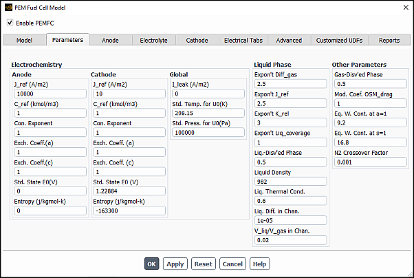
Electrochemistry
There are various parameters under Electrochemistry in the PEM Fuel Cell Model dialog box. For both the anode and the cathode, you can set the following parameters or leave the default values:
- J_ref
corresponds to
 and
and  , the reference exchange current density from
Equation 20–9 and
Equation 20–10.
, the reference exchange current density from
Equation 20–9 and
Equation 20–10.- C_ref
corresponds to the reference concentration (
 and
and  ) with units of 1
kgmol/m3 (see Equation 20–5 and
Equation 20–6).
) with units of 1
kgmol/m3 (see Equation 20–5 and
Equation 20–6).- Con. Exponent
corresponds to
 , the concentration dependence from Equation 20–5.
- Exch. Coeff. (a) , Exch. Coeff. (c)
are the transfer coefficients
 and
and  from Equation 20–5 and Equation 20–6,
respectively.
from Equation 20–5 and Equation 20–6,
respectively.- Std. State E0
are the reversible potentials
 and
and  in Equation 20–13 and Equation 20–14, respectively. This field appears
only when Use Half-Cell Potentials option is
selected under the Model tab.
in Equation 20–13 and Equation 20–14, respectively. This field appears
only when Use Half-Cell Potentials option is
selected under the Model tab.- Entropy
is the reaction entropy
 and
and  in Equation 20–13 and Equation 20–14.
- V_Open
corresponds to the constant value assigned to cathode half-cell potential
 and
and  . This parameter appears only when Use
Half-Cell Potentials option is not selected under the
Model tab.
. This parameter appears only when Use
Half-Cell Potentials option is not selected under the
Model tab.- I_leak
is the leakage current density (A/m2). It is used to compute the total leakage current
 (in Equation 20–55
through Equation 20–57)
by:
(in Equation 20–55
through Equation 20–57)
by:where
 is the electrolyte projected area (specified under
the Reports tab). When leakage through the
electrolyte occurs, the fuel cell generates less current especially
for cases with low values of fuel or air utilization. Note that you
can also specify the total leakage current through the user-defined
function
is the electrolyte projected area (specified under
the Reports tab). When leakage through the
electrolyte occurs, the fuel cell generates less current especially
for cases with low values of fuel or air utilization. Note that you
can also specify the total leakage current through the user-defined
function Leakge_Current(). For more information, see User-Accessible Functions.- Std. Temp. for U0 (K)
is the reference standard state temperature which is used for half-cell potentials computations in the Nernst equations (Equation 20–13 and Equation 20–14). This parameter appears only when the Use Half-Cell Potentials option is selected under the Model tab.
- Std. Press. for U0 (Pa)
is the reference standard state pressure which is used for half-cell potentials computations in the Nernst equations (Equation 20–13 and Equation 20–14). This parameter appears only when the Use Half-Cell Potentials option is selected under the Model tab.

Reference Diffusivity
The parameters in the Reference Diffusivity group box
appear only if the Multicomponent Diffusion option is
turned off in the Model tab. These parameters correspond to
the species mass diffusivity  from Equation 20–45.
Liquid Phase
When the Liquid Phase option is selected under the Model tab, you can specify the following parameters that appear in the Liquid Phase group box:
- Expon’t Diff_gas
corresponds to
 from Equation 20–45 for multiphase
PEMFC calculations.
from Equation 20–45 for multiphase
PEMFC calculations.- Expon’t J_ref
is the exponent
 that is used to modify
  and
and  according to Equation 20–38 to account for liquid blockage to
the reaction surface in Equation 20–5 through Equation 20–8.
according to Equation 20–38 to account for liquid blockage to
the reaction surface in Equation 20–5 through Equation 20–8.- Expon’t K_rel
is the exponent
 that is used to compute the relative permeability
in
that is used to compute the relative permeability
in  (Equation 20–31).
- Expon’t Liq_coverage
is the exponent
 that is used to compute the phase-change rates
 and
and  (Equation 20–26 and Equation 20–27).
- Liq.-Disv’ed Phase
is the mass exchange rate constant
 that is used to compute the rate of mass change
between liquid and dissolved phases
that is used to compute the rate of mass change
between liquid and dissolved phases  (Equation 20–27).
- Liquid Density , Liq. Thermal Cond.
are the density
 and thermal conductivity
  of liquid water, respectively. Note that the
effective thermal conductivity in porous media is computed
as:
of liquid water, respectively. Note that the
effective thermal conductivity in porous media is computed
as:
(32–1)
- Liq. Diff. in Chan.
is the
 in Equation 20–39. This parameter appears only when
the Compute Liquid In Channel option is
selected under the Model tab.
in Equation 20–39. This parameter appears only when
the Compute Liquid In Channel option is
selected under the Model tab.- V_liq/V_gas in Chan.
is the liquid to gas velocity ratio in the channel (
 in Equation 20–40). This parameter appears only
when the Compute Liquid In Channel option is
selected under the Model tab.
in Equation 20–40). This parameter appears only
when the Compute Liquid In Channel option is
selected under the Model tab.
Other Parameters
Under Other Parameters, you can specify the following:
- Gas-Disv’ed Phase
is the mass exchange rate constant
 that is used to compute the rate of mass change
between gas and dissolved phases
that is used to compute the rate of mass change
between gas and dissolved phases  (Equation 20–26).
- Mod. Coef. OSM_drag
is the constant
 with the default value of 1.0 that is used to
generalize the default osmotic drag coefficient
with the default value of 1.0 that is used to
generalize the default osmotic drag coefficient  (Equation 20–53).
- Eq. W. Cont. at a=1
is the equilibrium water content at the water activity of 1,
 , that is used in computing the equilibrium water
content
, that is used in computing the equilibrium water
content  (Equation 20–28).
- Eq. W. Cont. at s=1
is the equilibrium water content at water saturation of 1,
 , that is used in computing the equilibrium water
content
, that is used in computing the equilibrium water
content  (Equation 20–28). This item appears only if the
Liquid Phase option is selected under the
Model tab.
(Equation 20–28). This item appears only if the
Liquid Phase option is selected under the
Model tab.- N2 Crossover Factor
is the N2 crossover scaling factor (
 in Equation 20–23 in the Fluent Theory Guide, that is used in compute the
N2 crossover flux across the membrane).
This item appears only if the N2 Crossover
option is selected in the Model tab
(Options group).
in Equation 20–23 in the Fluent Theory Guide, that is used in compute the
N2 crossover flux across the membrane).
This item appears only if the N2 Crossover
option is selected in the Model tab
(Options group).- Desublimation Rate
is the ice phase desublimation rate (
 in Equation 20–42 in the Fluent Theory Guide. This item appears only if the
Ice Phase option is selected in the
Model tab (Options
group).
in Equation 20–42 in the Fluent Theory Guide. This item appears only if the
Ice Phase option is selected in the
Model tab (Options
group).- Sublimation Rate
is the ice phase sublimation rate (
 in Equation 20–42 in the Fluent Theory Guide. This item appears only if the
Ice Phase option is selected in the
Model tab (Options
group).
in Equation 20–42 in the Fluent Theory Guide. This item appears only if the
Ice Phase option is selected in the
Model tab (Options
group).
You can use the Anode tab of the PEM Fuel Cell Model dialog box to specify zones and properties of the current collector, the flow channel, the diffusion layer, the micro porous layer (optional), and the catalyst layer for the anode portion of the fuel cell.
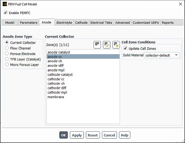
Under Anode Zone Type, select Current Collector.
From the Zone(s) selection list, select a corresponding zone. If you are modeling a fuel cell stack, then you must select all zones of a particular type as a group.
From the Solid Material drop-down list, select the appropriate material. You can use the Create/Edit Materials dialog box to customize solid materials. Note that for the Electrical Conductivity, you can only select a constant value in the Create/Edit Materials dialog box. The solid electrical conductivity value is the diffusivity of the solid phase potential in the solid zones.
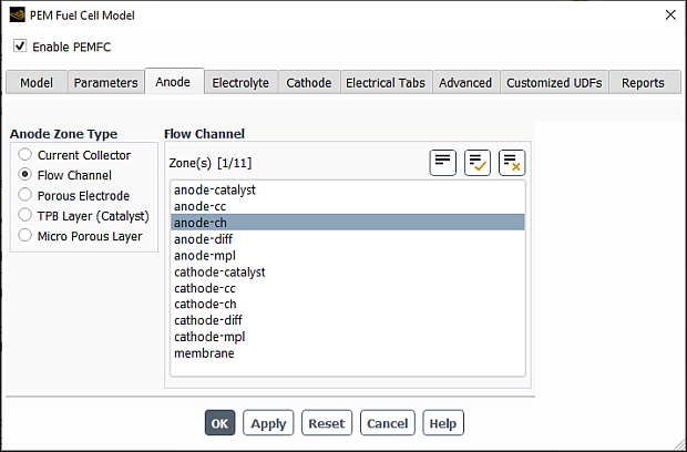
Under Anode Zone Type, select Flow Channel.
From the Zone(s) selection list, select an appropriate zone.
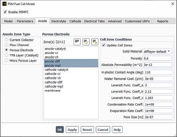
Under Anode Zone Type, select Porous Electrode.
From the Zone(s) selection list, select a corresponding zone. If you are modeling a fuel cell stack, then you must select all zones of a particular type as a group.
From the Solid Material drop-down list, select the appropriate material. You can use the Create/Edit Materials dialog box to customize solid materials. Note that for the Electrical Conductivity, you can only select a constant value in the Create/Edit Materials dialog box. The solid electrical conductivity value is the diffusivity of the solid phase potential in the solid zones.
Specify values for the following parameters:
- Porosity
is
 in Equation 20–45.
- Absolute Permeability
is
 in Equation 20–30.
- H-phobic Contact Angle
is the hydrophobic contact angle
 in Equation 20–36.
- Water Removal Coef.
is
 in Equation 20–35.
- Leverett Func. Coeff_a
is the Leverett function coefficient
 in Equation 20–37 (default =
1.417).
in Equation 20–37 (default =
1.417).- Leverett Func. Coeff_b
is the Leverett function coefficient
 in Equation 20–37 (default =
2.12).
in Equation 20–37 (default =
2.12).- Leverett Func. Coeff_c
is the Leverett function coefficient
 in Equation 20–37 (default =
1.263).
in Equation 20–37 (default =
1.263).- Condensation Rate Coeff.
is
 in Equation 20–34
- Evaporation Rate Coeff.
is
 in Equation 20–34
- Pore Size
is the average pore size,
 in Equation 20–105
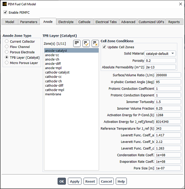
Under Anode Zone Type, select TPB Layer (Catalyst).
From the Zone(s) selection list, select a corresponding zone. If you are modeling a fuel cell stack, then you must select all zones of a particular type as a group.
From the Solid Material drop-down list, select the appropriate material. You can use the Create/Edit Materials dialog box to customize solid materials. Note that for the Electrical Conductivity, you can only select a constant value in the Create/Edit Materials dialog box. The solid electrical conductivity value is the diffusivity of the solid phase potential in the solid zones.
Specify values for the following parameters:
- Porosity
is
 in Equation 20–45.
- Absolute Permeability
is
 in Equation 20–30.
- Surface/Volume Ratio
is the specific active surface area
 in Equation 20–5.
- H-phobic Contact Angle
is the hydrophobic contact angle
 in Equation 20–36.
- Protonic Conduction Coefficient
is the model constant
 in Equation 20–49 (available only when
the Effective P-Conductivity in MEA
option is selected under the Model
tab).
in Equation 20–49 (available only when
the Effective P-Conductivity in MEA
option is selected under the Model
tab).- Protonic Conduction Exponent
is the model constant
 in Equation 20–48 (available only when
the Effective P-Conductivity in MEA
option is selected under the Model
tab).
in Equation 20–48 (available only when
the Effective P-Conductivity in MEA
option is selected under the Model
tab).- Ionomer Tortuosity
is the
 in Equation 20–49 (available only when
the Effective P-Conductivity in MEA
option is selected under the Model
tab).
in Equation 20–49 (available only when
the Effective P-Conductivity in MEA
option is selected under the Model
tab).- Ionomer Volume Fraction
is the
 in Equation 20–49 (available only when
the Effective P-Conductivity in MEA
option is selected under the Model
tab).
in Equation 20–49 (available only when
the Effective P-Conductivity in MEA
option is selected under the Model
tab).- Activation Energy for P-Cond
is the
 in Equation 20–48 (available only when
the Effective P-Conductivity in MEA
option is selected under the Model
tab).
in Equation 20–48 (available only when
the Effective P-Conductivity in MEA
option is selected under the Model
tab).- Activation Energy for J_ref
is the
 in Equation 20–9 (available only when
Temperature Dependent Jref is
enabled in the Model tab
(Options group box)).
in Equation 20–9 (available only when
Temperature Dependent Jref is
enabled in the Model tab
(Options group box)).- Reference Temperature for J_ref
is the
 in Equation 20–9 (available only when
Temperature Dependent Jref is
enabled in the Model tab
(Options group box)).
in Equation 20–9 (available only when
Temperature Dependent Jref is
enabled in the Model tab
(Options group box)).- Leverett Func. Coeff_a
is the Leverett function coefficient
 in Equation 20–37 (default =
1.417).
in Equation 20–37 (default =
1.417).- Leverett Func. Coeff_b
is the Leverett function coefficient
 in Equation 20–37 (default =
2.12).
in Equation 20–37 (default =
2.12).- Leverett Func. Coeff_c
is the Leverett function coefficient
 in Equation 20–37(default =
1.263).
in Equation 20–37(default =
1.263).- Condensation Rate Coeff.
is
 in Equation 20–34
- Evaporation Rate Coeff.
is
 in Equation 20–34
- Pore Size
is the average pore size,
 in Equation 20–105
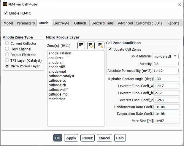
Under Anode Zone Type, select Micro Porous Layer.
From the Zone(s) selection list, select a corresponding zone. If you are modeling a fuel cell stack, then you must select all zones of a particular type as a group.
From the Solid Material drop-down list, select the appropriate material. You can use the Create/Edit Materials dialog box to customize solid materials. Note that for the Electrical Conductivity, you can only select a constant value in the Create/Edit Materials dialog box. The solid electrical conductivity value is the diffusivity of the solid phase potential in the solid zones.
Specify values for the following parameters:
- Porosity
is
 in Equation 20–45.
- Absolute Permeability
is
 in Equation 20–30.
- H-phobic Contact Angle
hydrophobic contact angle
 in Equation 20–36.
- Leverett Func. Coeff_a
is the Leverett function coefficient
 in Equation 20–37 (default =
1.417).
in Equation 20–37 (default =
1.417).- Leverett Func. Coeff_b
is the Leverett function coefficient
 in Equation 20–37 (default =
2.12).
in Equation 20–37 (default =
2.12).- Leverett Func. Coeff_c
is the Leverett function coefficient
 in Equation 20–37 (default =
1.263).
in Equation 20–37 (default =
1.263).- Condensation Rate Coeff.
is
 in Equation 20–34
- Evaporation Rate Coeff.
is
 in Equation 20–34
- Pore Size
is the average pore size,
 in Equation 20–105
For each case of the anode’s current collector, diffusion layer, micro porous layer, and catalyst layer, you assign a solid material and/or set the porosity and the viscous resistance. These settings represent setting a cell zone condition. With the Update Cell Zones option turned on (the default setting), this cell zone condition is applied to all selected zones in the Zone(s) list. If you want to set the cell zone conditions for each zone individually (using the Cell Zone Conditions task page), you should turn off the Update Cell Zones option.
You can use the Electrolyte tab of the PEM Fuel Cell Model dialog box to specify zones and properties of the electrolyte/membrane portion of the fuel cell.
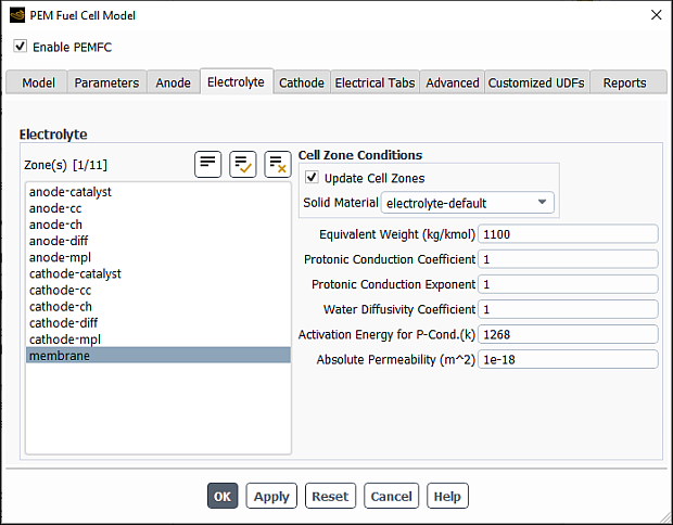
From the Zone(s) selection list, select a corresponding zone. If you are modeling a fuel cell stack, then you must select all zones of a particular type as a group.
From the Solid Material drop-down list, select the appropriate material. You can use the Create/Edit Materials dialog box to customize solid materials.
Specify values for the following parameters:
- Equivalent Weight
is the
 in Equation 20–26 and Equation 20–27.
- Protonic Conduction Coefficient
is the
 in Equation 20–49.
- Protonic Conduction Exponent
is the
 in Equation 20–48.
- Water Diffusivity Coefficient
is the
 in Equation 20–50.
- Activation Energy for P-Cond
is the
 in Equation 20–48 (available only when the
Effective P-Conductivity in MEA
option is selected under the Model
tab).
in Equation 20–48 (available only when the
Effective P-Conductivity in MEA
option is selected under the Model
tab).- Absolute Permeability
is the
 in Equation 20–30.
Note that the PEMFC model allows you to model the electrolyte/membrane as a solid zone only. However, it still allows for dissolved water, liquid or capillary pressure, and the ionic current to pass through.
When you assign a solid material to the membrane, you are setting a cell zone condition. With the Update Cell Zones option turned on (the default setting), this cell zone condition is applied to all selected zones in the Zone(s) list. If you want to set the cell zone conditions for each zone individually (using the Cell Zone Conditions task page), you should turn off the Update Cell Zones option.
You can use the Cathode tab of the PEM Fuel Cell Model dialog box to specify zones and properties of the current collector, the flow channel, the diffusion layer, the micro porous layer, and the catalyst layer for the cathode portion of the fuel cell.
The procedure for specifying the current collector properties for the cathode is similar to that for the anode. For specific steps, refer to Specifying Current Collector Properties for the Anode for details and then substitute “cathode” for “anode” where appropriate.
The procedure for specifying the flow channel properties for the cathode is similar to that for the anode. For specific steps, refer to Specifying Flow Channel Properties for the Anode and then substitute “cathode” for “anode” where appropriate.
The procedure for specifying the porous electrode properties for the cathode is similar to that for the anode. For specific steps, refer to Specifying Porous Electrode Properties for the Anode and then substitute “cathode” for “anode” where appropriate.
Figure 32.10: The Cathode Tab of the PEM Fuel Cell Model Dialog Box with TPB Layer (Catalyst) Selected
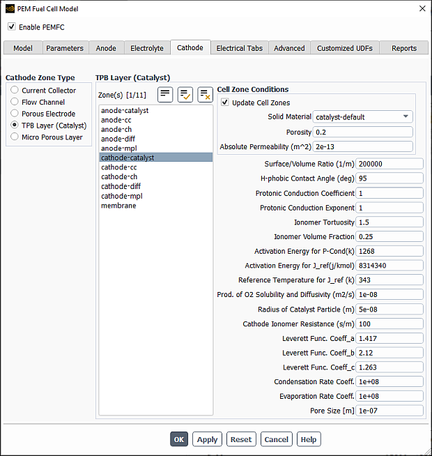
Under Cathode Zone Type, select TPB Layer (Catalyst).
From the Zone(s) selection list, select a corresponding zone. If you are modeling a fuel cell stack, then you must select all zones of a particular type as a group.
From the Solid Material drop-down list, select the appropriate material. You can use the Create/Edit Materials dialog box to customize solid materials. Note that for the Electrical Conductivity, you can only select a constant value in the Create/Edit Materials dialog box. The solid electrical conductivity value is the diffusivity of the solid phase potential in the solid zones.
Specify values for the following parameters:
- Porosity
is
 in Equation 20–45.
- Absolute Permeability
is
 in Equation 20–30.
- Surface/Volume Ratio
is the specific active surface area
 in Equation 20–6.
- H-phobic Contact Angle
is the hydrophobic contact angle
 in Equation 20–36.
- Protonic Conduction Coefficient
is the model constant
 in Equation 20–49 (available only when
the Effective P-Conductivity in MEA
option is selected under the Model
tab).
in Equation 20–49 (available only when
the Effective P-Conductivity in MEA
option is selected under the Model
tab).- Protonic Conduction Exponent
is the model constant
 in Equation 20–48 (available only when
the Effective P-Conductivity in MEA
option is selected under the Model
tab).
in Equation 20–48 (available only when
the Effective P-Conductivity in MEA
option is selected under the Model
tab).- Ionomer Tortuosity
is the
 in Equation 20–49 (available only when
the Effective P-Conductivity in MEA
option is selected under the Model
tab).
in Equation 20–49 (available only when
the Effective P-Conductivity in MEA
option is selected under the Model
tab).- Ionomer Volume Fraction
is the
 in Equation 20–49 (available only when
the Effective P-Conductivity in MEA
option is selected under the Model
tab).
in Equation 20–49 (available only when
the Effective P-Conductivity in MEA
option is selected under the Model
tab).- Activation Energy for P-Cond
is the
 in Equation 20–48 (available only when
the Effective P-Conductivity in MEA
option is selected under the Model
tab).
in Equation 20–48 (available only when
the Effective P-Conductivity in MEA
option is selected under the Model
tab).- Activation Energy for J_ref
is the
 in Equation 20–10 (available only when
Temperature Dependent Jref is
enabled in the Model tab
(Options group box)).
in Equation 20–10 (available only when
Temperature Dependent Jref is
enabled in the Model tab
(Options group box)).- Reference Temperature for J_ref
is the
 in Equation 20–10 (available only when
Temperature Dependent Jref is
enabled in the Model tab
(Options group box)).
in Equation 20–10 (available only when
Temperature Dependent Jref is
enabled in the Model tab
(Options group box)).
Besides the parameters for the catalyst layer listed above, you can also specify the following parameters for The Cathode Particle Model:
- Prod. Of O2 Solubility and Diffusivity
is
 in Equation 20–16.
- Radius of Catalyst Particle
is
 in Equation 20–16.
- Cathode Ionomer Resistance
is
 in Equation 20–15.
- Leverett Func. Coeff_a
is the Leverett function coefficient
in Equation 20–37 (default =
1.417).- Leverett Func. Coeff_b
is the Leverett function coefficient
in Equation 20–37 (default =
2.12).- Leverett Func. Coeff_c
is the Leverett function coefficient
in Equation 20–37 (default =
1.263).- Pore Size
is the average pore size,
 in Equation 20–105
The procedure for specifying the catalyst layer properties for the cathode is similar to that for the anode. For specific steps, refer to Specifying Micro Porous Layer (Optional) Properties for the Anode and then substitute “cathode” for “anode” where appropriate.
For each case of the cathode’s current collector, diffusion layer, micro porous layer, and catalyst layer, you assign a solid material and/or set the porosity and the viscous resistance. These settings represent setting a cell zone condition. With the Update Cell Zones option turned on (the default setting), this cell zone condition is applied to all selected zones in the Zone(s) list. If you want to set the cell zone conditions for each zone individually (using the Cell Zone Conditions task page), you should turn off the Update Cell Zones option.
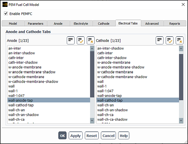
You can use the Electrical Tabs tab of the PEM Fuel Cell Model dialog box to specify Anode and Cathode Tabs. The anode and cathode tabs are the external wall surfaces where electrical potential (UDS0) boundary conditions are applied using the method selected in the Electrical System Setup group box (Model tab).
You can use the Advanced tab of the PEM Fuel Cell Model dialog box to specify the contact resistivity for any material interface in the geometry, set parameters for coolant channels, and define fuel stack units for managing stacks of fuel cells.
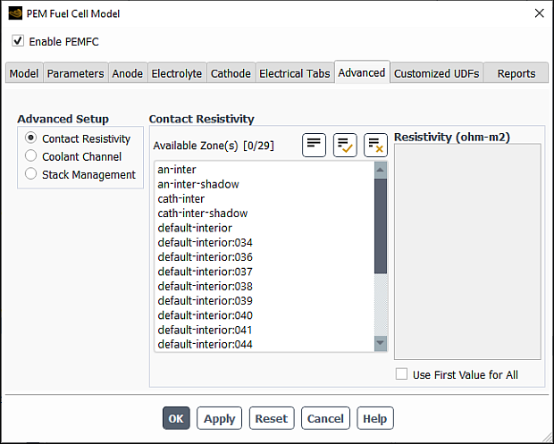
Under Advanced Setup, select Contact Resistivity.
From the Available Zone(s) selection list, select any number of corresponding interfaces. These zones are face zones over which a jump in electrical potential is caused by imperfect conduction.
Note: The contact resistance will be applied only to
wallandporous jumptypes of interfaces.Specify a value for the Resistivity for each specified zone.
Note that at porous jump and wall/wall-shadow interfaces, the contact resistivity is applied at each face. Therefore, you need to specify the resistivity only at one of the interface walls, otherwise the actual resistance will be doubled at the interface.
To simplify the input, you can choose to use the resistivity value of the first selected zone for all others as well by selecting the Use First Value for All option.
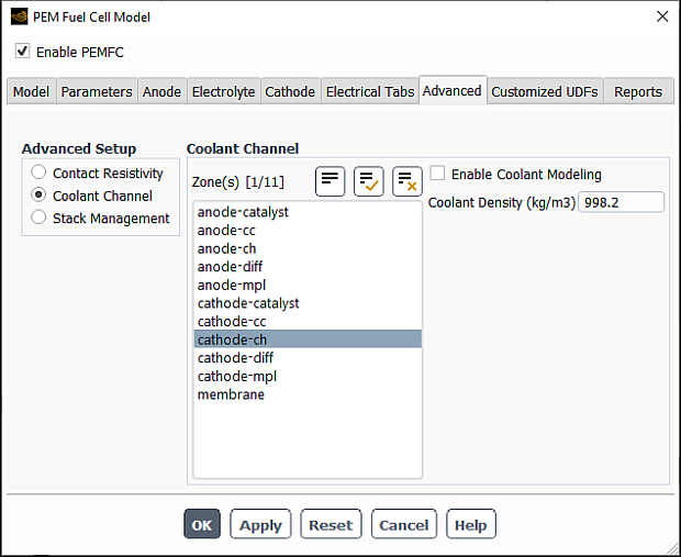
Under Advanced Setup, select Coolant Channel.
From the Zone(s) selection list, select any number of corresponding zones.
Specify a value for the Coolant Density.
To enable the coolant channel, select the Enable Coolant Modeling option. Amongst other settings, this will automatically create a new mixture material
pem+cool-mixtureconsisting ofhydrogen,oxygen,water-vapor,coolant-liquid, andnitrogen.The coolant species mixture material exists only in the coolant channel where its mass fraction is 1.0 and will have no effect on the gas phase in all other fluid zones. This is reflected in the mixture composition and in the density specification method for the mixture. All other mixture properties in the gas channels are automatically set to ideal-gas-mixing-law.
Using the Create/Edit Materials dialog box, set all other material properties for the new fluid
coolant-liquid.Specify the inlet and outlet conditions for cooling channels using standard boundary conditions dialog boxes.
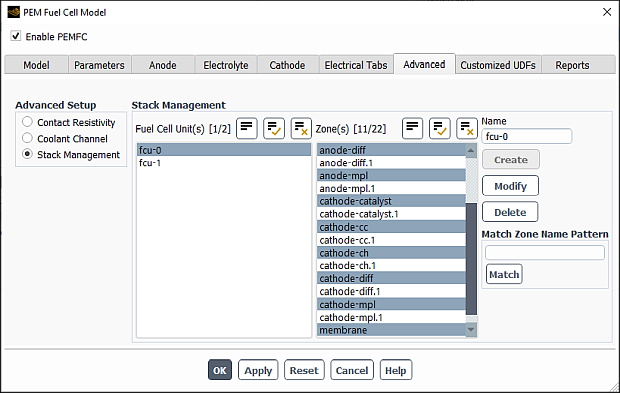
The Ansys Fluent PEMFC model allows you to model fuel cell stacks as well as individual fuel cells. In the Advanced tab of the PEM Fuel Cell Model dialog box, you can define fuel cell units for each fuel cell in a stack. A fuel cell unit consists of all zones of a single fuel cell in the stack.
Important: If you are only modeling a single fuel cell, then you do not need to set anything for Stack Management in the Advanced tab of the PEM Fuel Cell Model dialog box.
Select the Advanced tab of the PEM Fuel Cell Model dialog box.
Select Stack Management under Advanced Setup.
Since a fuel cell unit consists of all zones of a single fuel cell in the stack, select the corresponding zones from the Zone(s) list.
Create a new fuel cell unit by clicking the Create button. The new fuel cell is listed under Fuel Cell Unit(s) with a default name.
Edit a pre-existing fuel cell unit by selecting it in the Fuel Cell Unit(s) list. The zones in this fuel cell unit are automatically selected in the Zone(s) list. You can then modify the zones that make up the fuel cell unit and/or change its name in the Name field and click Modify to save the new settings.
Remove a pre-existing fuel cell unit by selecting it in the Fuel Cell Unit(s) list and clicking the Delete button.
Note: When deleting a unit, make sure that the electrical connectivity remains intact.
If your model contains many zone names, you can use the Match Zone Name Pattern field to specify a pattern to look for in the names of zones. Type the pattern in the text field and click Match to select (or deselect) the zones in the Zones list with names that match the specified pattern. You can match additional characters using
*and?. For example, if you specifywall*, all surfaces whose names begin with wall (for example, wall-1, wall-top) will be selected automatically. If they are all selected already, they will be deselected. If you specifywall?, all surfaces whose names consist of wall followed by a single character will be selected (or deselected, if they are all selected already).For example, in a stack there are many fuel cells, say 10–100, each having at least 9 zones (current collector, gas channel, diffusion layer, and catalyst layer for both anode and cathode and a membrane). Additionally, there may be coolant channels, and it may be that for mesh construction reasons each of these physical zones is made up of more than one mesh zone. Even for small stacks, you can easily end up having hundreds of cell zones in an Ansys Fluent mesh. Therefore, you may want to consider numbering the fuel cells in a stack and to use the assigned fuel cell number in the names of the mesh zones. When you set up your stacked fuel cell case, you would use the Match Zone Name Pattern field to pick all the zones belonging to a single fuel cell in the stack, rather than scrolling through the potentially very long list and selecting them manually.
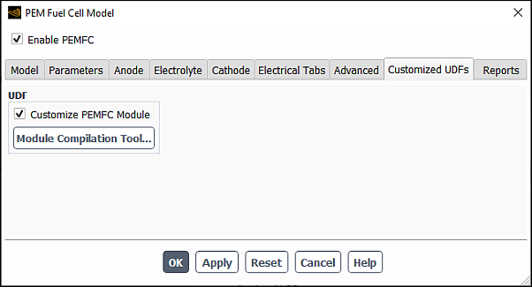
In the Customized UDFs tab, you can compile your user-defined function (UDF) in order to customize the PEM Fuel Cell Module. For information about compilers that can be used, see Compilers in the Fluent Customization Manual.
To compile your UDF:
In the UDF group box, enable Customize PEMFC Module.
Click
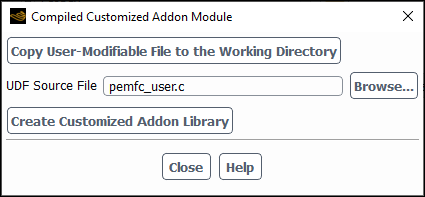
In the Compiled Customized Addon Module dialog box that opens, do one of the following:
If you want to create your UDF from a source file provided by Ansys Fluent:
Click Copy User-Modifiable File to the Working Directory to automatically copy the source code file from the Ansys Fluent installation directory to your working directory.
Note that depending on the fuel cell module you are using, the copied file will be different:
pemfc_user.c for the PEMFC model
pem_user.c for the Fuel Cell and Electrolysis models
constit.c for the SOFC model
Modify the copied source code file as desired.
If you want to use your existing source file:
Click next to UDF Source File to open the Select File dialog box.
Navigate to the desired directory and select the source file.
Click .
Click .
You can use the Reports tab of the PEM Fuel Cell Model dialog box to:
set up parameters for reporting data relevant to the fuel cell
use the calculator to compute the inlet boundary conditions that you can then enter in corresponding boundary conditions dialog boxes.
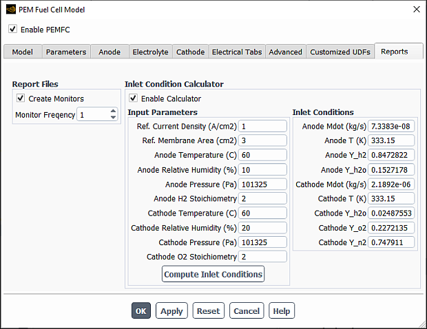
When you enable Create Monitors, then during the solution run, Ansys Fluent will write the following output files to monitor cell voltage, mean and minimum values of H2 mole fractions in anode fluid zones, mean and minimum values of O2 mole fractions in cathode fluid zones, and total current generated in anode and cathode catalyst zones:
cell-voltage.out
mean_h2.out
min_h2.out
mean_o2.out
min_o2.out
total-current-anode.out
total-current-cathode.out
You can specify the Monitor Frequency at which the monitoring data will be written during the calculation. For example, if you enter 10 in the Monitor Frequency text box, the output files will be updated after every 10 iterations.
If you want to use the inlet condition calculator, follow the below steps:
Select Enable Calculator in the Inlet Condition Calculator group box.
Enter the following Input Parameters:
Ref. Current Density: the current density that is used as a reference or target
Ref. Membrane Area: the membrane area that is used to compute the total current
Anode Temperature: the temperature at anode flow inlet (Celsius)
Anode Relative Humidity: the relative humidity at anode flow inlet as a percentage value
Anode Pressure: the system pressure in the anode flow channel (Pascal)
Anode H2 Stoichiometry: the hydrogen stoichiometry based upon the total current
Cathode Temperature: the temperature at cathode flow inlet (Celsius)
Cathode Relative Humidity: the relative humidity at cathode flow inlet as a percentage value
Cathode Pressure: the system pressure in the cathode flow channel (Pascal)
Cathode O2 Stoichiometry: the oxygen stoichiometry based upon the total current
Click Compute Inlet Conditions.
The resulting parameters are displayed in the Inlet Conditions group box:
Anode Mdot: the total mass flow rate at anode inlet(s) (kg/s)
Anode T: the temperature at anode flow inlet(s) (Kelvin)
Anode Y_h2: the mass fraction of hydrogen at anode flow inlet(s)
Anode Y_h2o: the mass fraction of water vapor at anode flow inlet(s)
Cathode Mdot: the total mass flow rate at cathode inlet(s) (kg/s)
Anode T: the temperature at cathode flow inlet(s) (Kelvin)
Anode Y_h2o: the mass fraction of water vapor at cathode flow inlet(s)
Anode Y_o2: the mass fraction of oxygen at cathode flow inlet(s)
Anode Y_n2: the mass fraction of nitrogen at cathode flow inlet(s)
Note:
The inlet condition calculator is used only to help you convert your input parameters to parameters that are recognized by Ansys Fluent. You still need to enter these values into relevant boundary conditions dialog boxes.
The converted values are based upon the total reference current of the cell or stack you specified. If multiple inlets are present in a cell or stack, you should exercise care when using the computed inlet conditions. For example, if you have two identical anode inlets, you need to split the computed total mass flow rates equally at each inlet.
Once you click the or button in the PEM Fuel Cell Model dialog box, Ansys Fluent automatically hooks several user-defined functions (UDFs) to the PEMFC solver. The UDFs either are hooked to corresponding PEMFC model parameters or perform specific operations, as shown in Table 32.1: User-Defined Functions for the PEMFC Module.
Note: If DEFINE_SOURCE user defined functions are not
hooked consistently with the PEMFC model settings, Ansys Fluent issues a warning
message in the console. You can restore the default source term settings by
closing and reopening the PEM Fuel Cell Model dialog
box and then clicking or
.
Table 32.1: User-Defined Functions for the PEMFC Module
| UDF Name | UDF Type | Description/Operation |
|---|---|---|
|
density |
DEFINE_PROPERTY | Density property for the pem+cool-mixture material. This UDF is used only if Enable Coolant Modeling is selected in the Advanced tab. |
|
diff |
DEFINE_DIFFUSIVITY | Mass diffusivity for the mixtures |
|
cond | DEFINE_DIFFUSIVITY | UDS diffusivity for the mixtures |
|
uds_flux | DEFINE_UDS_FLUX | Flux function for user-defined scalars (UDSs) |
|
source_s | DEFINE_SOURCE | Source terms in the catalyst zones for electric potential (UDS-0) |
|
source_m | DEFINE_SOURCE | Source terms in the catalyst zones for protonic potential (UDS-1) |
|
source_h2 | DEFINE_SOURCE | Source terms in the anode catalyst zones for species H2 |
|
source_o2 | DEFINE_SOURCE | Source terms in the cathode catalyst zones for species O2 |
|
source_h2o | DEFINE_SOURCE | Source terms in all fluid zones for species H2O |
|
source_mass | DEFINE_SOURCE | Source terms in all fluid zones for mass |
|
source_lambda | DEFINE_SOURCE | Source terms in the catalyst layers and membrane for the water content |
|
source_energy | DEFINE_SOURCE | Source terms in the fluid zones for the energy equation |
|
source_liquid | DEFINE_SOURCE | Source terms in the porous layers and catalyst layers for capillary pressure (UDS-2) |
|
source_chan_liq | DEFINE_SOURCE | Source terms in the flow channels for liquid saturation in the channel equation |
|
source_momentum | DEFINE_SOURCE | Source terms in the flow channels for the momentum equations |
|
initialize | DEFINE_INIT | Initializes solution |
|
adjust | DEFINE_ADJUST | Adjust function (executed at every iteration) |
|
unsteady | DEFINE_UDS_UNSTEADY | Unsteady function for UDSs (transient simulations only) |
|
write_sec_hdf | DEFINE_RW_HDF_FILE | - |
|
read_sec_hdf | DEFINE_RW_HDF_FILE |
- |
|
pem_lib_load | DEFINE_EXECUTE_ON_LOADING |
- |
|
exec_at_end | DEFINE_EXECUTE_AT_END |
- |
|
set_new_stack_voltage | DEFINE_ON_DEMAND |
- |
|
set_new_stack_current | DEFINE_ON_DEMAND |
- |
|
get_old_stack_voltage | DEFINE_ON_DEMAND |
- |
|
get_old_stack_current | DEFINE_ON_DEMAND |
- |
|
list_pemfc_udf | DEFINE_ON_DEMAND | Lists all used UDSs and UDMs |
|
report_current | DEFINE_ON_DEMAND | Reports the total current |
|
aniso_econd | DEFINE_ANISOTROPIC_DIFFUSIVITY | UDS diffusivity for electric potential. This UDF is used only when Anisotropic E-cond. in GDL/MPL is enabled in the Model tab. |
The following boundary conditions need to be defined for the PEMFC simulation based on your problem specification:
Anode Inlet
Mass flow rate
Temperature
Direction specification method
Mass fractions (for example, h2, and h2o)
The coolant must be set to zero if coolant channels are enabled
UDS-4 (Water Saturation in Channels) must be set to zero
Cathode Inlet
Mass flow rate
Temperature
Direction specification method
Mass fractions (for example o2, h2o, and n2)
The coolant must be set to zero if coolant channels are enabled
UDS-4 (Water Saturation in Channels) must be set to zero
Coolant Inlet (if any)
Mass flow rate
Temperature
Direction specification method
Coolant mass fraction set to 1
UDS-4 (Water Saturation in Channels) must be set to zero
Pressure Outlets (all)
Realistic backflow conditions.
Terminal Anode
Temperature (or heat flux if known)
(when Set Up in B.C. Panels is selected as the Electrical System Setup method in the Model tab) Electric potential
In the UDS tab of the Wall dialog box for the anode tab, set Electric Potential (UDS-0) to ground voltage (zero). Note that for the anode tab, the voltage must be anchored to zero, whether you want to specify the total voltage or current density condition for the cathode tab.
Terminal Cathode
Temperature (or heat flux if known)
(when Set Up in B.C. Panels is selected as the Electrical System Setup method in the Model tab) Electric potential
In the UDS tab of the Wall dialog box for the cathode tab, set Electric Potential (UDS-0) to:
voltage (V) of the cathode when using the Specified Value option, or
current density (A/m2) when using the Specified Flux option.
Note that the sign of the UDS-0 flux on the cathode side should be negative since the current (positive charge) is leaving the cathode electrical terminal.
For potentiostatic boundary conditions, after initialization, solutions are calculated easily for cell voltages close to the open-circuit voltage. The same can be said for galvanostatic boundary conditions and low electric current. By lowering the cell voltage or by raising the average electric current, you can calculate subsequent stationary solutions.
In the event of convergence problems, it is recommended that you change the
multigrid cycle to F-cycle with BCGSTAB
(bi-conjugate gradient stabilized method) selected as the stabilization method for
the species and the two potential equations. For the species and the user-defined
scalar equations, it may be necessary to reduce the termination (criteria) of the
multigrid-cycles to  . For stack simulations, the termination criterion may be reduced
to
. For stack simulations, the termination criterion may be reduced
to  for the two potential equations.
Also, it may be useful to turn off Joule Heating and Reaction Heating in the PEM Fuel Cell Model dialog box (in the Model tab) for the first few (approximately 5-10) iterations after initialization. This allows the two electric potentials to adjust from their initial values to more physical values, avoiding the possibility of extreme electrochemical reactions and electric currents that would in turn adversely impact the solution.
You can perform postprocessing using standard Ansys Fluent quantities and by using user-defined scalars and user-defined memory allocations. By default, the Ansys Fluent PEMFC model defines several user-defined scalars and user-defined memory allocations, described in Table 32.2: User-Defined Scalar Allocations and Table 32.3: User-Defined Memory Allocations.
Table 32.2: User-Defined Scalar Allocations
| UDS Name | Description |
UDS 0
| Electric Potential (solid phase potential) (Volts) |
UDS 1
| Protonic Potential (membrane phase potential) (Volts) |
UDS 2
| Capillary Pressure |
UDS 3
| Water Content |
UDS 4
| Liquid Saturation in Channels |
Table 32.3: User-Defined Memory Allocations
| UDM Name | Description |
UDM 0
| X Current Flux Density (A/m2) |
UDM 1
| Y Current Flux Density (A/m2) |
UDM 2
| Z Current Flux Density (A/m2) |
UDM 3
| Current Flux Density Magnitude (A/m2) |
UDM 4
| Ohmic Heat Source (W/m3) |
UDM 5
| Reaction Heat Source (W/m3) |
UDM 6
| Overpotential (Volts) |
UDM 7
| Evaporation to Vapor Phase Change
Source (kg/m3-s) ( in Equation 20–30 in the Fluent Theory Guide) in Equation 20–30 in the Fluent Theory Guide) |
UDM 8
| Osmotic Drag Coefficient |
UDM 9
| Water Activity |
UDM 10
| Equilibrium Water Content |
UDM 11
| Absorption from Vapor phase change
source (kg/m3-s) ( in Equation 20–25 in the Fluent Theory Guide) in Equation 20–25 in the Fluent Theory Guide) |
UDM 12
| Absorption from Liquid Phase Change
Source (kg/m3-s) ( in Equation 20–25 in the Fluent Theory Guide) in Equation 20–25 in the Fluent Theory Guide) |
UDM 13
| Transfer Current (A/m3) |
UDM 14
| Liquid Saturation in Porous Media |
UDM 15
| GDL Liquid Removal (kg/m3-s) |
UDM 16
| Osmotic Drag Source (kg/m3-s) |
UDM 17
| Capillary Pressure (Pa) |
UDM 18
| Pressure Gradient Source (kg/m3-s) |
You can obtain this list by opening the Execute On Demand dialog box and pulling down the Function drop-down list.
![]() User Defined → User
Defined →
User Defined → User
Defined →
and access the execute-on-demand function called
list_pemfc_udf.
Alternatively, you can view the listing that appears when you first load your
PEMFC case, or you can type list_pemfc_udf in the text user
interface and the listing will appear in the console window.
Note:
For field variables that are stored in UDM, use the corresponding variables for postprocessing. Postprocessing the UDM itself is not recommended.
For reviewing simulation results in CFD-Post for cases involving UDM or UDS, export the solution data as CFD-Post-compatible file (.cdat) in Fluent and then load this file into CFD-Post.
Important: When you load older PEM Fuel Cell cases into Ansys Fluent, and you are monitoring a UDS using volume or surface monitors, make sure you re-visit the corresponding monitors dialog box (for example, the Volume Monitor or the Surface Monitor dialog box) to verify that the correct UDS name is used for the appropriate monitor.
In addition, you can generate graphical plots or alphanumeric reports of the following variable (available under the Species... category):
- N2 crossover
is the mass transfer rate of N2 due to the crossover effect (
 in Equation 20–22 in the Fluent Theory Guide). This item is available only when the
N2 Crossover option is selected in the
Model tab (Options group).
in Equation 20–22 in the Fluent Theory Guide). This item is available only when the
N2 Crossover option is selected in the
Model tab (Options group).
- Ice formation rate
is the formation rate of the ice phase (
 in Equation 20–42 in the Fluent Theory Guide). This item is available only turbulent
simulations when the Ice Phase option is selected
in the Model tab (Options
group).
in Equation 20–42 in the Fluent Theory Guide). This item is available only turbulent
simulations when the Ice Phase option is selected
in the Model tab (Options
group). - Ice formation rate
is the ice volume fraction (
 in Equation 20–41 in the Fluent Theory Guide). This item is available only turbulent
simulations when the Ice Phase option is selected
in the Model tab (Options
group).
in Equation 20–41 in the Fluent Theory Guide). This item is available only turbulent
simulations when the Ice Phase option is selected
in the Model tab (Options
group).
As noted in Properties, you
can directly incorporate your own formulations and data for the properties of the
fuel cell membrane using the pemfc_user.c source code
file.
The following listing represents a description of the contents of the
pemfc_user.c source code file:
-
real Get_P_sat(real T, cell_t c, Thread *t) Returns the value of the water vapor saturation pressure as a function of temperature (Equation 20–54) or other user-specified values.
-
real Water_Activity(real P, real T, cell_t c, Thread
                            *t)
Returns the value of water activity (Equation 20–29).
-
real Osmotic_Drag_Coefficient(cell_t c, Thread *t) Returns the value of the osmotic drag coefficient (Equation 20–53).
-
real Membrane_Conductivity(real lam, cell_t c, Thread
                            *t)
Returns the value of the protonic conductivity in MEA (Equation 20–48).
-
real Water_Content_Diffusivity(real lam, real T, real
                            mem_mol_density,cell_tc,Thread*t)
Returns the value of the water content diffusivity in the MEA (Equation 20–50).
-
real Gas_Diffusivity(cell_t c, Thread *t, int
                            j_spe)
Returns the value of the gaseous species diffusivities in the channels, gas diffusion layers, micro porous layers, and catalysts (Equation 20–45).
-
real MCD_Gas_Diffusivity(cell_t c, Thread *t, int
                            i)
Returns the tortuosity-corrected value of the gas species diffusion coefficients computed with the multicomponent diffusion option (Equation 20–45).
-
real Compute_Js(real s, Thread *t) Computes the Leverett function; namely, the
 -
- relation (Equation 20–36).
-
Real Capillary_P_Diffusivity(real sat, real K_abs, cell_t c,
                            Thread *t)
Returns the
 in Equation 20–30.
-
real Water_Content(cell_t c, Thread *t) Computes the water content
 .
.-
real Anode_AV_Ratio(cell_t c, Thread *t) Returns the value of the specific active surface area (
 in Equation 20–5) for the anode
catalyst.
in Equation 20–5) for the anode
catalyst.-
real Cathode_AV_Ratio(cell_t c, Thread *t) Returns the value of the specific active surface area (
 in Equation 20–6) for the cathode
catalyst.
in Equation 20–6) for the cathode
catalyst.-
real Anode_J_TransCoef(cell_t c, Thread *t) Returns the value of the anode reaction reference current density
 used in Equation 20–5.
-
real Cathode_J_TransCoef(cell_t c, Thread *t) Returns the value of the cathode reaction reference current density
 used in Equation 20–6.
-
real Open_Cell_Voltage(cell_t c, Thread *t) Returns the value of the half-cell potential
 used in Equation 20–11 and Equation 20–12.
-
real Leakage_Current(cell_t c, Thread *t) Returns the value of the total leakage current (
 in Equation 20–55 through
Equation 20–57).
in Equation 20–55 through
Equation 20–57).-
real resistance_in_channel (real sat) Returns momentum resistance as a function of liquid saturation in gas channels.
-
void Set_UDS_Names(char
                            uds[n_uds_required][STRING_SIZE])
Used to rename user-defined scalars (UDSs). Note that the units of the user defined scalars cannot be changed.
void Set_UDS_Names(char uds[n_uds_required][STRING_SIZE])
 {
      strncpy(uds[0], "Electric Potential", STRING_SIZE-1);
      strncpy(uds[1], "Protonic Potential", STRING_SIZE-1);
      strncpy(uds[2], "Cap. Pressure", STRING_SIZE-1);
      strncpy(uds[3], "Water Content", STRING_SIZE-1);
      strncpy(uds[4], "Liq. Saturation in Channels",  STRING_SIZE-1);
 }
If you want to change the names of UDSs, change the second argument of the
strncpyfunctions, recompile and link the module as with any modification topemfc_user.c. Note thatSTRING_SIZEis fixed inpemfc.hand should not be changed.Important: When you load older PEM Fuel Cell cases into Ansys Fluent, and you are monitoring a UDS using volume or surface monitors, make sure you re-visit the corresponding monitors dialog box (for example, the Volume Monitor or the Surface Monitor dialog box) to make sure that the correct UDS name is used for the appropriate monitor.
-
void Set_UDM_Names(char
                            udm[n_udm_required][STRING_SIZE])
Used to rename user defined memory (UDMs). Note that the units of user defined memory cannot be changed.
void Set_UDM_Names(char udm[n_udm_required][STRING_SIZE])
 {
     strncpy(udm[0], "X Current Flux Density",  STRING_SIZE-1);
     strncpy(udm[1], "Y Current Flux Density",  STRING_SIZE-1);
     strncpy(udm[2], "Z Current Flux Density",  STRING_SIZE-1);
     strncpy(udm[3], "Current Flux Density Magnitude", STRING_SIZE-1);
     strncpy(udm[4], "Ohmic Heat Source", STRING_SIZE-1);
     strncpy(udm[5], "Reaction Heat Source",  STRING_SIZE-1);
     strncpy(udm[6], "Overpotential", STRING_SIZE-1);
     strncpy(udm[7], "Evaporation to Vapor", STRING_SIZE-1);
     strncpy(udm[8], "Osmotic Drag Coefficient", STRING_SIZE-1);
     strncpy(udm[9], "Water Activity", STRING_SIZE-1);
     strncpy(udm[10], "Equilibrium Water Content",  STRING_SIZE-1);
     strncpy(udm[11], "Absorption from Vapor", STRING_SIZE-1);
     strncpy(udm[12], "Absorption from Liquid", STRING_SIZE-1);
     strncpy(udm[13], "Transfer Current",  STRING_SIZE-1);
     strncpy(udm[14], "Liquid Saturation",  STRING_SIZE-1);
     strncpy(udm[15], "GDL Liquid Removal",  STRING_SIZE-1);
     strncpy(udm[16], "Osmotic Drag Source (PEM)", STRING_SIZE-1);
     strncpy(udm[17], "Cap. Pressure", STRING_SIZE-1);
     strncpy(udm[18], "Pressure Gradient Source", STRING_SIZE-1);
 }
If you want to change the names of UDMs, change the second argument of the
strncpyfunctions, recompile and link the module as with any modification topemfc_user.c. Note thatSTRING_SIZEis fixed inpemfc.hand should not be changed.Important: When you load older PEM Fuel Cell cases into Ansys Fluent, and you are monitoring a UDM using volume or surface monitors, make sure you re-visit the corresponding monitors dialog box (for example, the Volume Monitor or the Surface Monitor dialog box) to make sure that the correct UDM name is used for the appropriate monitor.
-
real electric_contact_resistance(face_t f, Thread *t, int
                            ns)
Returns the value for the electrical contact resistance.
-
real Transfer_Current(real i_ref, real gamma, int species_i,
                            real alpha_a, real alpha_c, real *dRade, real *dRcde, Thread *t, cell_t
                            c, real cathode_volume)
Computes the transfer current (
 ), corresponding to
  in Equation 20–5 and
  in Equation 20–6.
Inputs for this function include:
i_refeffective transfer current coefficient, computed by Cathode_J_TransCoef(c,t)orAnode_J_TransCoef(c,t)gammacathode or anode concentration exponent species_ispecies index used in fuel cells (for example i_o2, i_h2,i_h2o)alpha_aproduct of anode exchange coefficient and 
alpha_cproduct of cathode exchange coefficient and 
tcurrent thread ccurrent cell cathode_volumetotal volume of cathode catalyst layer Outputs for this function include:
sourceanode or cathode volumetric transfer current (  in Equation 20–5 or
 in Equation 20–6)
 *dRadepartial derivative of  with respect to activation loss
*dRcdepartial derivative of  with respect to activation loss
-
Thermal_ctk_pemfc(face_t f, Thread *t) Used to change the constant value of Thermal Contact Resistance set in the Porous Jump dialog box to a locally variable value.
-
Phase_Change_const(cell_t c, Thread *t) Used to change the constant value of
 used to compute the gas-liquid phase change
rate.
used to compute the gas-liquid phase change
rate.-
Equilibrium_Water_Content (cell_t c, Thread *t, real act, real
                            sat)
Used to change the equilibrium water content computation in Equation 20–28 in the Fluent Theory Guide.
Additional inputs for this function include:
actwater activity (  in Equation 20–28 in the Fluent Theory Guide)
satliquid saturation (  in Equation 20–28 in the Fluent Theory Guide)