


The procedure for setting up and solving fuel cell problems using the Fuel Cell and Electrolysis Model is described in detail in this chapter. Refer to the following sections for more information:
- 32.2.1. Overview and Limitations
- 32.2.2. Geometry Definition for the Fuel Cell and Electrolysis Model
- 32.2.3. Installing the Fuel Cell and Electrolysis Model
- 32.2.4. Loading the Fuel Cell and Electrolysis Module
- 32.2.5. Workflow for Using the Fuel Cell and Electrolysis Module
- 32.2.6. Setting Up the Fuel Cell and Electrolysis Module
- 32.2.7. Modeling Current Collectors
- 32.2.8. Fuel Cell and Electrolysis Model Boundary Conditions
- 32.2.9. Solution Guidelines for the Fuel Cell and Electrolysis Model
- 32.2.10. Postprocessing the Fuel Cell and Electrolysis Model
- 32.2.11. User-Accessible Functions
The Ansys Fluent Fuel Cell and Electrolysis Model are made up of several user-defined functions (UDFs) and a graphical user interface. The potential fields are solved as user-defined scalars. The liquid water saturation,  , and the water content,
  , are also solved as user-defined scalars. The electrochemical reactions occurring on the catalyst are modeled through various source terms while other model parameters are handled through the user interface. The Fuel Cell and Electrolysis Model can be used in parallel Ansys Fluent as well.
Note the following limitation when using the Fuel Cell and Electrolysis model:
The anisotropic species diffusivity option is not compatible with the Fuel Cell and Electrolysis model.
Due to the fact that there is a number of different physical zones associated with the fuel cell, the following regions must be present in the fuel cell mesh:
Anode flow channel
Anode gas diffusion layer
Anode catalyst layer
Membrane layer
Cathode catalyst layer
Cathode gas diffusion layer
Cathode flow channel
The following zones have to be identified, if present in the fuel cell mesh:
Anode current collector
Cathode current collector
Coolant channel
The Fuel Cell and Electrolysis Model is provided as an add-on module with the standard
Ansys Fluent licensed software. The module is installed with the standard installation
of Ansys Fluent in a directory called addons/fuelcells in your
installation area. The Fuel Cell and Electrolysis Model consists of a UDF library
and a pre-compiled Scheme library, which must be loaded and activated before
calculations can be performed.
The Fuel Cell and Electrolysis module can be loaded only after a valid Ansys Fluent case file has been set or read.
There are two different ways in which you can load the Fuel Cell and Electrolysis module into Ansys Fluent:
Through the ribbon
In the Physics ribbon tab, click (Models group), and select Fuel Cell & Electrolysis Model....
 Physics →
Models → More
→ Fuel Cell & Electrolysis
Model...
Physics →
Models → More
→ Fuel Cell & Electrolysis
Model...Once the Fuel Cell and Electrolysis module is loaded into Ansys Fluent, the Fuel Cell and Electrolysis Models dialog box opens where you can set an appropriate model as described in Specifying Cathode Properties (Cathode Tab).
Through the text user interface (TUI)
The text command to load the add-on module is
define→models→addon-moduleA list of Ansys Fluent add-on modules is displayed:
> /define/models/addon-module
Fluent  Addon Modules:
     0. None
     1. MHD Model
     2. Fiber Model
     3. Fuel Cell and Electrolysis Model
     4. SOFC Model with Unresolved Electrolyte
     5. Population Balance Model
     6. Adjoint Solver
     7. Single Potential Battery Module
     8. MSMD Battery Model
     9. PEM Fuel Cell Model
Enter Module Number: [0] 3
Select the Fuel Cell and Electrolysis Model by entering the module number
3.
During the loading process, a Scheme library (containing the graphical and text user interface) and a UDF library (containing a set of user defined functions) are loaded into Ansys Fluent.
The Fuel Cell and Electrolysis Model can be used to model polymer electrolyte membrane fuel cells (PEMFC), solid oxide fuel cells (SOFC), and the process of high-temperature electrolysis. The following describes an overview of the procedure required in order to use the Fuel Cell and Electrolysis Model in Ansys Fluent.
Start Ansys Fluent.
Read the case file.
Scale the grid, if necessary.
Use the Fuel Cell and Electrolysis Models dialog box to define the fuel cell model parameters.
Define material properties.
Set the operating conditions.
Set the boundary conditions.
Start the calculations.
Save the case and data files.
Process your results.
Important:
The Fuel Cell and Electrolysis Models dialog box greatly simplifies the input of parameters and boundary conditions, but it does not replace the boundary conditions interface. Therefore, it is a good policy to start the setup with the Fuel Cell and Electrolysis Models dialog box and do the finishing steps for boundary conditions afterwards.
Note that the majority of this chapter describes how to set up the Ansys Fluent Fuel Cell and Electrolysis Model using the graphical user interface. You can also perform various tasks using the text user interface. For more information, see Using the Fuel Cell and Electrolysis Text User Interface.
Once the module has been loaded, in order to set fuel cell model parameters and assign properties to the relevant regions in your fuel cell, you need to access the fuel cell graphical user interface (the Fuel Cell and Electrolysis Models dialog box).
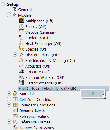
The Fuel Cell and Electrolysis Models dialog box can be accessed either through the ribbon (as described in Loading the Fuel Cell and Electrolysis Module) or from the Setup/Models/Fuel Cells and Electrolysis tree item.
![]() Setup → Models
→ Fuel Cells and Electrolysis
Setup → Models
→ Fuel Cells and Electrolysis ![]() Edit...
Edit...
By default, the PEMFC model is already enabled, however, you can also choose the SOFC or the SOEC models.
Using the Fuel Cell and Electrolysis Models dialog box, you can identify the relevant zones for the current collectors, flow channels, gas diffusion layers, catalyst layers, and the membrane/electrolyte. You can specify the following inputs using the Fuel Cell and Electrolysis Models dialog box. Optional inputs are indicated as such.
Enable the appropriate type of fuel cell model, either PEMFC, SOFC, or SOEC.
Enable either the single-phase or the multi-phase fuel cell model (if PEMFC is selected).
Set the appropriate options for the fuel cell model (optional).
Set the various parameters for the fuel cell model.
Select the appropriate zones and specify the properties on the anode side.
Select the appropriate zones and specify the properties of the membrane/electrolyte.
Select the appropriate zones and specify the properties on the cathode side.
Provide input for advanced features such as contact resistivities, coolant channel properties, or stack management settings (optional).
Set solution controls such as under-relaxation factors (optional).
Provide input to assist reporting (optional).
Refer to the following sections for more information:
- 32.2.6.1. Specifying Model Options (Model Tab)
- 32.2.6.2. Specifying Model Parameters (Parameters Tab)
- 32.2.6.3. Specifying Anode Properties (Anode Tab)
- 32.2.6.4. Specifying Electrolyte/Membrane Properties (Electrolyte Tab)
- 32.2.6.5. Specifying Cathode Properties (Cathode Tab)
- 32.2.6.6. Setting Advanced Properties (Advanced Tab)
- 32.2.6.7. Customizing the Fuel Cell and Electrolysis Module
- 32.2.6.8. Reporting on the Solution (Reports Tab)
The Model tab of the Fuel Cell and Electrolysis Models dialog box allows you to turn on or off various options when solving a fuel cell problem. To model polymer electrolyte membrane fuel cells, enable the PEMFC option in the Model tab. Likewise, to model solid oxide fuel cells, enable the SOFC option in the Model tab. Finally, to model electrolysis, enable the SOEC option in the Model tab.
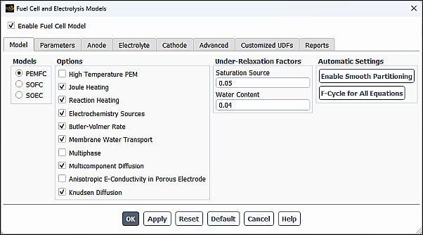
Several fuel cell model options are available in the Model tab of the Fuel Cell and Electrolysis Models dialog box including:
The High Temperature PEM option enables the high-temperature PEMFC model (see High-Temperature PEMFC in the Fluent Theory Guide for more information). When this option is not selected, Ansys Fluent uses the low-temperature PEMFC model.
The Joule Heating option takes into account ohmic heating. This option includes the
 term in the energy source term from Equation 20–82 in the
calculations.
term in the energy source term from Equation 20–82 in the
calculations.The Reaction Heating option takes into account the heat generated by the electrochemical reactions, which includes the
 term, and the product of transfer current and the
over-potentials in the energy source term from Equation 20–82 in the calculations.
term, and the product of transfer current and the
over-potentials in the energy source term from Equation 20–82 in the calculations.The Electrochemistry Sources option allows the Fuel Cell and Electrolysis Model to take electrochemistry effects into account. If you are only interested in the basic flow field throughout the fuel cell, you can turn off the Electrochemistry Sources option in order to suppress most effects of the Fuel Cell and Electrolysis Model. To turn off all effects of the Fuel Cell and Electrolysis Model, you should also turn off the Membrane Water Transport and Multiphase options.
The Butler-Volmer Rate option (the default) is used to compute the transfer currents inside the catalyst layers. If this option is turned off, the Tafel approximation (Equation 20–69) is used.
The Membrane Water Transport option takes into account the transport of water across the membrane. This option is only available for the low-temperature PEMFC model (that is, the High Temperature PEM option is not selected).
The Multiphase option takes into account multiphase calculations. Use this option if you are solving for approximate liquid transport in the gas diffusion layer of the fuel cell (low-temperature PEMFC only).
The Multicomponent Diffusion option is used to compute the gas species mass diffusivity using the full multicomponent diffusion method as described in Equation 20–89, as opposed to the default option that uses Equation 20–87.
The Anisotropic E-cond in GDL/MPL option is used to model the typically non-isotropic electrical conductivity. It is applicable only for porous electrodes (gas diffusion layers).
Due to the fibrous structure of the porous material that is used for the electrodes (or gas diffusion layer), the electrical conductivity is typically non-isotropical, with the cross-plane components being orders of magnitude smaller than the in-plane components. This can be modeled using the Anisotropic E-cond in GDL/MPL setting. When this option is enabled, the Electrical Conductivity for the solid material used in the electrolyte is no longer used. Instead, you need to specify, for this solid material, the electrical conductivity by choosing one of the three non-isotropical options for the UDS diffusivity (
UDS-0). The three options are: anisotropic; orthotropic; and cyl-orthotropic. For more information about these UDS Diffusivity options, refer to the Ansys Fluent User's Guide.For example, to use this feature, perform the following steps:
Select the Anisotropic E-cond in GDL/MPL option in the Model tab of the Fuel Cell and Electrolysis Models dialog box.
In the Create/Edit Materials dialog box, select
defined-per-udsfor UDS Diffusivity for the solid material that is to be used for the porous electrode.Select one of the three options for UDS-0: anisotropic; orthotropic; or cyl-orthotropic and set the appropriate values.
Important: Note that, in this case, the Electrical Conductivity for this solid material is ignored.
The Knudsen Diffusion option includes the effect of Knudsen diffusion in the calculation of the effective gas diffusivity using Equation 20–89 in the Fluent Theory Guide.
For low-temperature PEMFC problems, you can use the Under-Relaxation Factors fields to influence the solution process.
The saturation source term
 in Equation 20–84 usually requires
under-relaxation. You can change the default value for the
under-relaxation factor by changing the value for Saturation
Source.
in Equation 20–84 usually requires
under-relaxation. You can change the default value for the
under-relaxation factor by changing the value for Saturation
Source.The water content,
 , in Equation 20–95 also may need
under-relaxation. You can change the default value for the
under-relaxation factor by changing the value for Water
Content.
, in Equation 20–95 also may need
under-relaxation. You can change the default value for the
under-relaxation factor by changing the value for Water
Content.
Under Automatic Settings, the following parallel multigrid solver control parameters are available:
: Enables the smooth partitioning process when running in Parallel.
When this option is enabled, the fuel cell parallel solver:
Uses the Metis method for partitioning the mesh
Enables Laplace Smoothing
Partitions and distributes the mesh data to all compute nodes
: Sets the multigrid cycle type to F cycle for all equations that are being solved. This control overrides the equation cycle settings in the Advanced Solution Controls dialog box.
Nearly all options are turned on by default. You may want to override the default values, depending on the problem you want to model. For instance, if you are not concerned with the heat generated due to chemical reaction, then you may want to turn off the Reaction Heating option.
You can use the Parameters tab of the Fuel Cell and Electrolysis Models dialog box to specify the electrochemistry parameters for the Fuel Cell and Electrolysis Model, reference diffusivities for the reactants, among other model parameters.
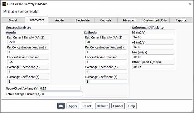
There are various parameters under Electrochemistry in the Fuel Cell and Electrolysis Models dialog box. For both the anode and the cathode, you can also set the following parameters or leave the default values.
The Ref. Current Density corresponds to
 and
and  , the reference exchange current density from Equation 20–66 and Equation 20–67.
The Ref. Concentration corresponds to the reference concentration (
 and
and  ) with units of 1
  (see Equation 20–66 and Equation 20–67).
The Concentration Exponent corresponds to
 , the concentration dependence from Equation 20–66.
The Exchange Coefficient (a) and Exchange Coefficient (c) correspond to the transfer coefficients,
 and
and  , from Equation 20–66 and Equation 20–67.
The Open-Circuit Voltage corresponds to
 in Equation 20–71.
The Leakage Current corresponds to
 in Equation 20–99 through Equation 20–104.
This is the total amount of transfer current (A) due to fuel-oxidant
cross-over (leakage through the electrolyte). When this happens, the
fuel cell generates less current especially for cases with low values of
fuel or air utilization. In addition to the constant value you can
specify in the Electrochemistry tab, you can also
specify the leakage current through the user-defined function
in Equation 20–99 through Equation 20–104.
This is the total amount of transfer current (A) due to fuel-oxidant
cross-over (leakage through the electrolyte). When this happens, the
fuel cell generates less current especially for cases with low values of
fuel or air utilization. In addition to the constant value you can
specify in the Electrochemistry tab, you can also
specify the leakage current through the user-defined function
Leakge_Current(). For more information, see User-Accessible Functions.
Moreover, the following parameters can also be set here:
The Reference Diffusivities correspond to
 from Equation 20–87, the species mass
diffusivity. These are not be required if the Multicomponent
Diffusion option is enabled in the
Model tab.
from Equation 20–87, the species mass
diffusivity. These are not be required if the Multicomponent
Diffusion option is enabled in the
Model tab.The Pore Blockage for Gas Diffusion corresponds to
 from Equation 20–87 for multiphase PEMFC
calculations.
from Equation 20–87 for multiphase PEMFC
calculations.The Pore Blockage for Transfer Current is used to account for liquid blockage to the reaction surface by modifying
 and
and  in Equation 20–66 through Equation 20–69 as
follows:
in Equation 20–66 through Equation 20–69 as
follows:where
 is the pore blockage for transfer current.
The Exponent for relative permeability corresponds to
 in Equation 20–85.

Note that, conventionally, the negative voltage is supplied to the cathode side in power consuming devices such as electrolyzers. Ansys Fluent adopts the inverse notation where the negative voltage is supplied to the anode side whilst cathode remains positively charged. The main reason for this discrepancy is that the same infrastructure is used for both the electrolysis and fuel cells models. Usage of the terms "anode" and "cathode" in this manual and in the user interface should be interpreted according to conventions for power-supplying devices.
You can use the Anode tab of the Fuel Cell and Electrolysis Models dialog box to specify zones and properties of the current collector, the flow channel, the diffusion layer, and the catalyst layer for the anode portion of the fuel cell.
Figure 32.21: The Anode Tab of the Fuel Cell and Electrolysis Models Dialog Box With Current Collector Selected
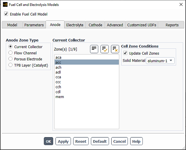
Select the Anode tab of the Fuel Cell and Electrolysis Models dialog box.
Select Current Collector under Anode Zone Type.
Select a corresponding zone from the Zone(s) list. If you are modeling a fuel cell stack, then you must pick all zones of a particular type as a group.
Select a Solid Material from the corresponding drop-down list. Solid materials can be customized using the Create/Edit Materials dialog box. Note that for the Electrical Conductivity, you can only choose a constant value in the Create/Edit Materials dialog box. The solid electrical conductivity value is the diffusivity of the solid phase potential in the solid zones.
Figure 32.22: The Anode Tab of the Fuel Cell and Electrolysis Models Dialog Box With Flow Channel Selected
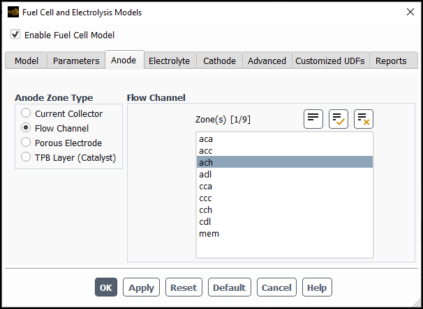
Select the Anode tab of the Fuel Cell and Electrolysis Models dialog box.
Select Flow Channel under Anode Zone Type.
Select a corresponding zone from the Zone(s) list.
Figure 32.23: The Anode Tab of the Fuel Cell and Electrolysis Models Dialog Box With Porous Electrode Selected
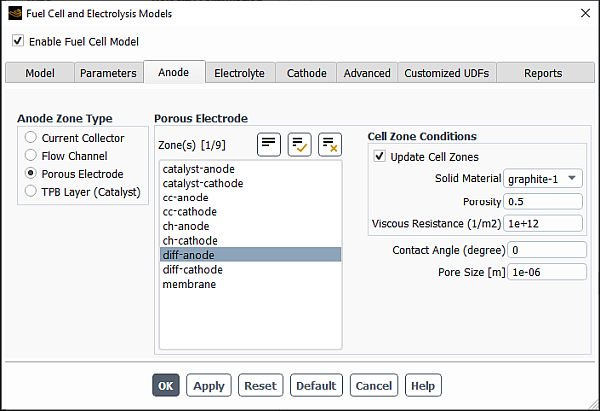
Select the Anode tab of the Fuel Cell and Electrolysis Models dialog box.
Select Porous Electrode under Anode Zone Type.
Select a corresponding zone from the Zone(s) list. If you are modeling a fuel cell stack, then you must pick all zones of a particular type as a group.
Select a Solid Material from the corresponding drop-down list. Solid materials can be customized using the Create/Edit Materials dialog box. Note that for the Electrical Conductivity, you can only choose a constant value in the Create/Edit Materials dialog box. The solid electrical conductivity value is the diffusivity of the solid phase potential in the solid zones.
Specify a value for the Porosity.
Specify a value for the Viscous Resistance.
Specify a value for the Contact Angle for multiphase fuel cell calculations (
 in Equation 20–86).
Specify the average Pore Size (
 in Equation 20–105).
Figure 32.24: The Anode Tab of the Fuel Cell and Electrolysis Models Dialog Box With TPB Layer (Catalyst) Selected
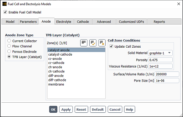
Select the Anode tab of the Fuel Cell and Electrolysis Models dialog box.
Select TPB Layer (Catalyst) under Anode Zone Type.
Select a corresponding zone from the Zone(s) list. If you are modeling a fuel cell stack, then you must pick all zones of a particular type as a group.
Select a Solid Material from the corresponding drop-down list. Solid materials can be customized using the Create/Edit Materials dialog box. Note that for the Electrical Conductivity, you can only choose a constant value in the Create/Edit Materials dialog box. The solid electrical conductivity value is the diffusivity of the solid phase potential in the solid zones.
Specify a value for the Porosity.
Specify a value for the Viscous Resistance.
Specify a value for the Surface/Volume Ratio (the specific active surface area in Equation 20–66).
Specify a value for the Contact Angle for multiphase fuel cell calculations (
 in Equation 20–86).
Specify the average Pore Size (
in Equation 20–105).
For each case of the anode’s current collector, diffusion layer, and catalyst layer, you assign a solid material and/or set the porosity and the viscous resistance. These settings represent setting a cell zone condition. With the Update Cell Zones option turned on (the default setting), this cell zone condition is applied to all selected zones in the Zone(s) list. If you want to set the cell zone conditions for each zone individually (using the Cell Zone Conditions task page), you should turn off the Update Cell Zones option.
You can use the Electrolyte tab of the Fuel Cell and Electrolysis Models dialog box to specify zones and properties of the electrolyte/membrane portion of the fuel cell (for example, Figure 32.25: The Electrolyte Tab of the Fuel Cell and Electrolysis Models Dialog Box for the low-temperature PEMFC).
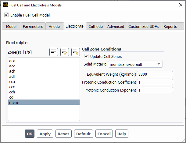
Select a corresponding zone from the Zone(s) list. If you are modeling a fuel cell stack, then you must pick all membrane zones as a group.
Select a Solid Material from the corresponding drop-down list. Solid materials can be customized using the Create/Edit Materials dialog box.
(low-temperature PEMFC only) Specify a value for the Equivalent Weight (
 in Equation 20–93).
(low-temperature PEMFC only) Specify a value for the Protonic Conduction Coefficient (
 in Equation 20–91). This is used to calculate
the membrane phase electric conductivity.
in Equation 20–91). This is used to calculate
the membrane phase electric conductivity.(low-temperature PEMFC only) Specify a value for the Protonic Conduction Exponent (
 in Equation 20–91).
Note that the Fuel Cell and Electrolysis Model allows you to model the electrolyte/membrane as either a fluid zone or as a solid zone. For PEMFC, the Fuel Cell and Electrolysis Model still allows for water and the ionic current to pass through the electrolyte/membrane.
When you assign a solid material to the membrane, you are setting a cell zone condition. With the Update Cell Zones option turned on (the default setting), this cell zone condition is applied to all selected zones in the Zone(s) list. If you want to set the cell zone conditions for each zone individually (using the Cell Zone Conditions task page), you should turn off the Update Cell Zones option.
You can use the Cathode tab of the Fuel Cell and Electrolysis Models dialog box to specify zones and properties of the current collector, the flow channel, the diffusion layer, and the catalyst layer for the cathode portion of the fuel cell.
Figure 32.26: The Cathode Tab of the Fuel Cell and Electrolysis Models Dialog Box With Current Collector Selected
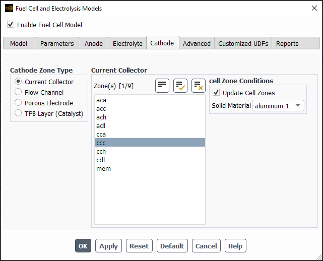
Select the Cathode tab of the Fuel Cell and Electrolysis Models dialog box.
Select Current Collector under Cathode Zone Type.
Select a corresponding zone from the Zone(s) list. If you are modeling a fuel cell stack, then you must pick all zones of a particular type as a group.
Select a Solid Material from the corresponding drop-down list. Solid materials can be customized using the Create/Edit Materials dialog box. Note that for the Electrical Conductivity, you can only choose a constant value in the Create/Edit Materials dialog box. The solid electrical conductivity value is the diffusivity of the solid phase potential in the solid zones.
Figure 32.27: The Cathode Tab of the Fuel Cell and Electrolysis Models Dialog Box With Flow Channel Selected
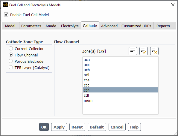
Select the Cathode tab of the Fuel Cell and Electrolysis Models dialog box.
Select Flow Channel under Cathode Zone Type.
Select a corresponding zone from the Zone(s) list. If you are modeling a fuel cell stack, then you must pick all zones of a particular type as a group.
Figure 32.28: The Cathode Tab of the Fuel Cell and Electrolysis Models Dialog Box With Porous Electrode Selected
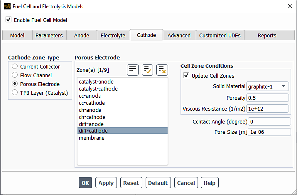
Select the Cathode tab of the Fuel Cell and Electrolysis Models dialog box.
Select Porous Electrode under Cathode Zone Type.
Select a corresponding zone from the Zone(s) list. If you are modeling a fuel cell stack, then you must pick all zones of a particular type as a group.
Select a Solid Material from the corresponding drop-down list. Solid materials can be customized using the Create/Edit Materials dialog box. Note that for the Electrical Conductivity, you can only choose a constant value in the Create/Edit Materials dialog box. The solid electrical conductivity value is the diffusivity of the solid phase potential in the solid zones.
Specify a value for the Porosity.
Specify a value for the Viscous Resistance.
Specify a value for the Contact Angle for multiphase fuel cell calculations (
 in Equation 20–86).
Specify the average Pore Size (
in Equation 20–105).
Figure 32.29: The Cathode Tab of the Fuel Cell and Electrolysis Models Dialog Box With TPB Layer (Catalyst) Selected
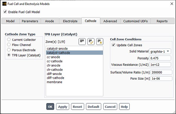
Select the Cathode tab of the Fuel Cell and Electrolysis Models dialog box.
Select TPB Layer(Catalyst) under Cathode Zone Type.
Select a corresponding zone from the Zone(s) list. If you are modeling a fuel cell stack, then you must pick all zones of a particular type as a group.
Select a Solid Material from the corresponding drop-down list. Solid materials can be customized using the Create/Edit Materials dialog box. Note that for the Electrical Conductivity, you can only choose a constant value in the Create/Edit Materials dialog box. The solid electrical conductivity value is the diffusivity of the solid phase potential in the solid zones.
Specify a value for the Porosity.
Specify a value for the Viscous Resistance.
Specify a value for the Surface/Volume Ratio (the specific active surface area in Equation 20–67).
Specify a value for the Contact Angle for multiphase fuel cell calculations (
 in Equation 20–86).
Specify the average Pore Size (
in Equation 20–105).
For each case of the cathode’s current collector, diffusion layer, and catalyst layer, you assign a solid material and/or set the porosity and the viscous resistance. These settings represent setting a cell zone condition. With the Update Cell Zones option turned on (the default setting), this cell zone condition is applied to all selected zones in the Zone(s) list. If you want to set the cell zone conditions for each zone individually (using the Cell Zone Conditions task page), you should turn off the Update Cell Zones option.
You can use the Advanced tab of the Fuel Cell and Electrolysis Models dialog box to specify the contact resistivity for any material interface in the geometry, set parameters for coolant channels, and define fuel stack units for managing stacks of fuel cells.
Figure 32.30: The Advanced Tab of the Fuel Cell and Electrolysis Models Dialog Box for Contact Resistivities
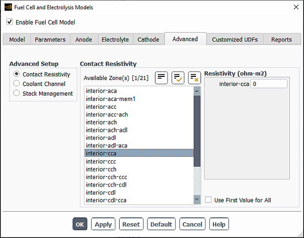
Select the Advanced tab of the Fuel Cell and Electrolysis Models dialog box.
Select Contact Resistivity under Advanced Setup.
Select any number of corresponding interfaces from the Available Zone(s) list. These zones are face zones over which a jump in electrical potential is caused by imperfect conduction.
Specify a value for the Resistivity for each specified zone.
Note that at porous jump and wall/wall-shadow interfaces, the contact resistivity is applied at each face. Therefore, you need to specify the resistivity only at one of the interface walls, otherwise the actual resistance will be doubled at the interface.
To simplify the input, you can choose to use the resistivity value of the first selected zone for all others as well by turning on the Use First Value for All option.
Figure 32.31: The Advanced Tab of the Fuel Cell and Electrolysis Models Dialog Box for the Coolant Channel
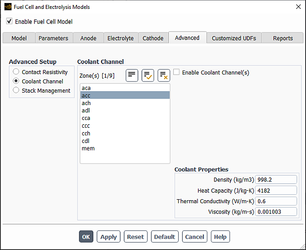
Select the Advanced tab of the Fuel Cell and Electrolysis Models dialog box.
Select Coolant Channel under Advanced Setup.
Select any number of corresponding zones from the Zone(s) list.
Specify a value for the Density.
Specify a value for the Heat Capacity.
Specify a value for the Thermal Conductivity.
Specify a value for the Viscosity.
To enable the coolant channel, turn on the Enable Coolant Channel(s) option. Amongst other settings, this will change the mixture to include the coolant species, which is otherwise absent.
Figure 32.32: The Advanced Tab of the Fuel Cell and Electrolysis Models Dialog Box for Stack Management
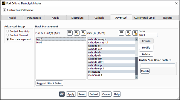
The Ansys Fluent Fuel Cell and Electrolysis Model allows you to model fuel cell stacks as well as individual fuel cells. In the Advanced tab of the Fuel Cell and Electrolysis Models dialog box, you can define fuel cell units for each fuel cell in a stack. A fuel cell unit consists of all zones of a single fuel cell in the stack.
Important: If you are only modeling a single fuel cell, then you do not need to set anything for Stack Management in the Advanced tab of the Fuel Cell and Electrolysis Models dialog box.
Select the Advanced tab of the Fuel Cell and Electrolysis Models dialog box.
Select Stack Management under Advanced Setup.
Since a fuel cell unit consists of all zones of a single fuel cell in the stack, select the corresponding zones from the Zone(s) list.
Create a new fuel cell unit by clicking the Create button. The new fuel cell is listed under Fuel Cell Unit(s) with a default name.
Edit a pre-existing fuel cell unit by selecting it in the Fuel Cell Unit(s) list. The zones in this fuel cell unit are automatically selected in the Zone(s) list. You can then modify the zones that make up the fuel cell unit and/or change its name in the Name field and click Modify to save the new settings.
Remove a pre-existing fuel cell unit by selecting it in the Fuel Cell Unit(s) list and clicking the Delete button.
If your model contains many zone names, you can use the Match Zone Name Pattern field to specify a pattern to look for in the names of zones. Type the pattern in the text field and click Match to select (or deselect) the zones in the Zones list with names that match the specified pattern. You can match additional characters using
*and?. For example, if you specifywall*, all surfaces whose names begin with wall (for example, wall-1, wall-top) will be selected automatically. If they are all selected already, they will be deselected. If you specifywall?, all surfaces whose names consist of wall followed by a single character will be selected (or deselected, if they are all selected already).For example, in a stack there are many fuel cells, say 10–100, each having at least 9 zones (current collector, gas channel, diffusion layer, and catalyst layer for both anode and cathode and a membrane). Additionally, there may be coolant channels, and it may be that for mesh construction reasons each of these physical zones is made up of more than one mesh zone. Even for small stacks, you can easily end up having hundreds of cell zones in an Ansys Fluent mesh. Therefore, you may want to consider numbering the fuel cells in a stack and to use the assigned fuel cell number in the names of the mesh zones. When you set up your stacked fuel cell case, you would use the Match Zone Name Pattern field to pick all the zones belonging to a single fuel cell in the stack, rather than scrolling through the potentially very long list and selecting them manually.
You can have Ansys Fluent attempt to automatically determine the zones that constitute a single fuel cell in a stack using the Suggest Stack Setup button. Manually performing this task is often time-consuming and error-prone. Using the Suggest Stack Setup button can save you from having to manually enter this information yourself for potentially hundreds of zones.
When using the Suggest Stack Setup button, Ansys Fluent needs to correctly identify electrically conducting parts and their connectivity (anode, electrolyte, cathode, coolant channels, and external contacts) using zone information generally required by the fuel cell model anyway. Ansys Fluent requires zone information to have been specified in all of the following tabs in the Fuel Cell and Electrolysis Models dialog box:
In the Anode tab, specify zone information for the current collector, the porous electrode, and the TPB catalyst layer.
In the Electrolyte tab, specify zone information for the electrolyte/membrane.
In the Cathode tab, specify zone information for the current collector, the porous electrode, and the TPB catalyst layer.
In the Advanced tab, specify zone information for the coolant channel.
In the Reports tab, specify the external contact interface(s).
In the Advanced tab, click the Suggest Stack Setup button.
Important: If your fuel cell model inputs are incorrect (or incomplete), Ansys Fluent cannot completely be sure that the resulting setup is correct. Also, even if your inputs are correct, an unconventional fuel cell design may cause Ansys Fluent to suggest an inaccurate stack setup. So, it is your responsibility to verify the stack setup prior to clicking either the or the buttons.
In the Customized UDFs tab, you can compile your user-defined function (UDF) in order to customize the Fuel Cell and Electrolyses module.
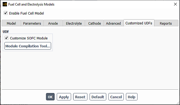
See Customizing the PEM Fuel Cell Module for details on how to compile your UDF.
You can use the Reports tab of the Fuel Cell and Electrolysis Models dialog box to set up parameters that will be useful in reporting data relevant to the fuel cell.
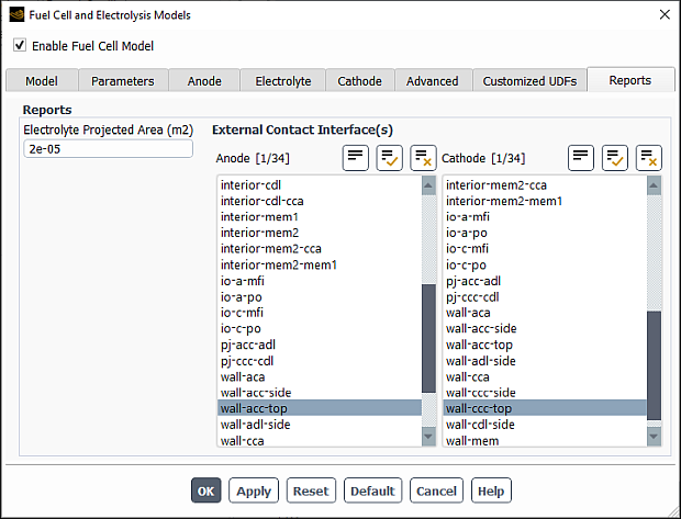
The Electrolyte Projected Area field requires the projected area of the Membrane Electrolyte Assembly (MEA) and is only used to calculate the average current density. The assembly consists of the membrane and the catalyst layers above and below the membrane. The value of the projected area can be computed from the Projected Surface Areas dialog box.
![]() Results → Reports
→ Projected Areas
Results → Reports
→ Projected Areas ![]() Edit...
Edit...
The External Contact Interface(s) fields requires the face zones that act as external contact surfaces for the anode and the cathode.
These inputs are used to report cell voltage. For potentiostatic boundary conditions, this is the difference between the provided values, but for galvanostatic boundary conditions, the cell voltage is part of the solution.
In previous versions of Ansys Fluent, user-defined scalar (UDS) equations could only be solved in fluid zones. This restriction is now removed. As a result, the Fuel Cell and Electrolysis module allows you to model current collectors as solid, as well as fluid zones. One advantage of using solids as the current collector is that the convergence of the species equations are not hindered by the potentially skewed mesh inside the current collectors.
If fluid zones are used to model solid current collectors, Ansys Fluent automatically sets velocities to zero and cuts off species transport into these zones. If solid zones are used, however, you need to activate the solution of the electric potential (UDS-0) in these solid zones (see the separate Ansys Fluent User’s Guide for details). The value of the Electrical Conductivity for the solid material must be assigned in the Create/Edit Materials dialog box.
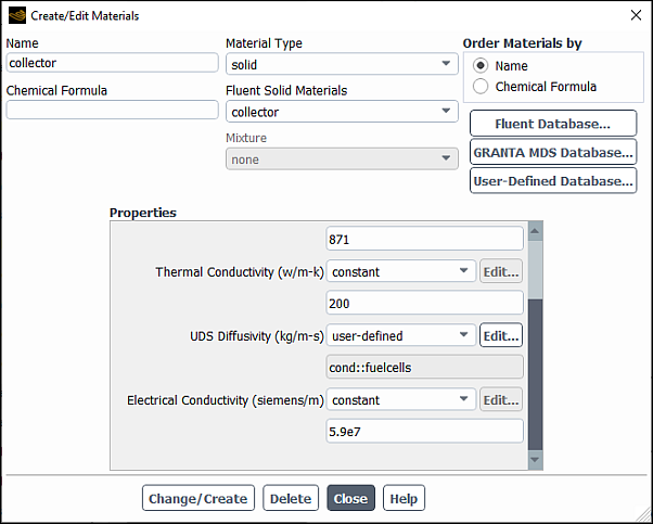
Important: Note that the UDS Diffusivity should be set to
user-defined (cond::fuelcells). Do not use the
defined-per-uds option.
For more information on the user-defined scalar diffusivity, see the separate Ansys Fluent User's Guide.
Note that the Fuel Cell and Electrolysis Model allows you to model current collectors either as porous media zones (if you want to allow for mass and momentum transport within the collectors) or as solid zones.
The following boundary conditions need to be defined for the Fuel Cell and Electrolysis simulation based on your problem specification:
Anode Inlet
Mass flow rate
Temperature
Direction specification method
Mass fractions (for example, h2, and h2o).
The coolant must be set to zero if coolant channels are enabled.
UDS-2 (Water Saturation) must be set to
0
Cathode Inlet
Mass flow rate
Temperature
Direction specification method
Mass fractions (for example o2, h2o, and n2).
The coolant must be set to zero if coolant channels are enabled.
UDS-2 (Water Saturation) must be set to
0
Coolant Inlet (if any)
Mass flow rate
Temperature
Direction specification method
Coolant mass fraction set to
1UDS-2 (Water Saturation) must be set to
0
Pressure Outlets (all)
Realistic backflow conditions.
Terminal Anode
Temperature (or flux if known)
UDS-0 (electric potential) set to ground voltage
Terminal Cathode
Temperature (or flux if known)
UDS-0 (electric potential) is set to the voltage of the cathode (if solving to constant voltage), or the UDS-0 (electric potential) flux is set to the current density in
 (SI units) (if solving for constant current). Note
that the sign of the UDS-0 flux on the cathode side is
negative.
(SI units) (if solving for constant current). Note
that the sign of the UDS-0 flux on the cathode side is
negative.
For potentiostatic boundary conditions, after initialization, steady-state solutions are calculated easily for cell voltages close to the open-circuit voltage. The same can be said for galvanostatic boundary conditions and low electric current. By lowering the cell voltage or by raising the average electric current, you can calculate subsequent stationary solutions.
In the event of convergence problems, it is recommended that you change the
multigrid cycle to F-cycle with BCGSTAB
(bi-conjugate gradient stabilized method) selected as the stabilization method for
the species and the two potential equations. For the species and the user-defined
scalar equations, it may be necessary to reduce the termination (criteria) of the
multigrid-cycles to  . For stack simulations, the termination criterion may be reduced
to
. For stack simulations, the termination criterion may be reduced
to  for the two potential equations.
Also, it may be useful to turn off Joule Heating and Reaction Heating in the Fuel Cell and Electrolysis Models dialog box (in the Model tab) for the first few (approximately 5-10) iterations after initialization. This allows the two electric potentials to adjust from their initial values to more physical values, avoiding the possibility of extreme electrochemical reactions and electric currents that would in turn adversely impact the solution.
You can perform postprocessing using standard Ansys Fluent quantities and by using user-defined scalars and user-defined memory allocations. By default, the Ansys Fluent Fuel Cell and Electrolysis Model defines several user-defined scalars and user-defined memory allocations, described in Table 32.4: User-Defined Scalar Allocations and Table 32.5: User-Defined Memory Allocations.
Table 32.4: User-Defined Scalar Allocations
| UDS Name | Description |
UDS 0
| Electric Potential (solid phase potential) (Volts) |
UDS 1
| Protonic Potential (membrane phase potential) (Volts) |
UDS 2
| Water Saturation (liquid saturation) |
UDS 3
| Water Content |
Table 32.5: User-Defined Memory Allocations
| UDM Name | Description |
UDM 0
| X Current Flux Density ( ) ) |
UDM 1
| Y Current Flux Density ( ) ) |
UDM 2
| Z Current Flux Density ( ) ) |
UDM 3
| Current Flux Density Magnitude ( ) ) |
UDM 4
| Ohmic Heat Source ( ) ) |
UDM 5
| Reaction Heat Source ( ) ) |
UDM 6
| Overpotential (Volts) |
UDM 7
| Phase Change Source ( ) ) |
UDM 8
| Osmotic Drag Coefficient |
UDM 9
| Liquid Water Activity |
UDM 10
| Membrane Water Content |
UDM 11
| Protonic Conductivity (1/ohm-m) |
UDM 12
| Back Diffusion Mass Source ( ) ) |
UDM 13
| Transfer Current ( ) ) |
UDM 14
| Osmotic Drag Source ( ) ) |
You can obtain this list by opening the Execute On Demand dialog box and pulling down the Function drop-down list.
![]() User Defined → User
Defined →
User Defined → User
Defined →
and access the execute-on-demand function called
list_pemfc_udf.
Alternatively, you can view the listing that appears when you first load your Fuel
Cell and Electrolysis case, or you can type list_pemfc_udf
in the text user interface and the listing will appear in the console window.
Note:
For field variables that are stored in UDM, use the corresponding variables for postprocessing. Postprocessing the UDM itself is not recommended.
For reviewing simulation results in CFD-Post for cases involving UDM or UDS, export the solution data as CFD-Post-compatible file (.cdat) in Fluent and then load this file into CFD-Post.
Important: When you load older Fuel Cell and Electrolysis cases into Ansys Fluent, and you are monitoring a UDS using volume or surface monitors, make sure you re-visit the corresponding monitors dialog box (for example, the Volume Monitor or the Surface Monitor dialog box) to verify that the correct UDS name is used for the appropriate monitor.
As noted in Properties,
you can directly incorporate your own formulations and data for the properties of
the fuel cell membrane using the pem_user.c source code
file.
The following listing represents a description of the contents of the
pem_user.c source code file:
-
real Get_P_sat(real T, cell_t c, Thread *t) Returns the value of the water vapor saturation pressure as a function of temperature (Equation 20–98) or other user-specified values.
-
real Water_Activity(realP, realT, cell_t c, Thread
                            *t)
Returns the value of water activity (Equation 20–96).
-
real Water_Content(real act) Returns the value of the membrane water content at the membrane catalyst interface (Equation 20–95).
-
real Osmotic_Drag_Coefficient(real P, real T, cell_t c, Thread
                            *t)
Returns the value of the osmotic drag coefficient (Equation 20–92).
-
real Membrane_Conductivity(real lam, cell_t c, Thread
                            *t)
Returns the value of the membrane’s protonic conductivity (Equation 20–91).
-
real Electrolyte_Conductivity(cell_t c, Thread *t) Returns the value of the ionic conductivity in the electrolyte (Equation 20–90). (SOFC and Electrolysis only)
-
real Water_Content_Diffusivity(real lam, real T, real
                            mem_mol_density,cell_tc,Thread*t)
Returns the value of the water content diffusivity in the membrane (Equation 20–94).
-
real Gas_Diffusivity(cell_tc, Thread *t, int j_spe) Returns the value of the gaseous species diffusivities in the channels, gas diffusion layers and catalysts (Equation 20–87).
-
real MCD_Gas_Diffusivity(cell_t c, Thread *t, int
                            i)
Returns the tortuosity-corrected value of the gas species diffusion coefficients computed with the multicomponent diffusion option (Equation 20–89).
-
real Saturation_Diffusivity(real sat, real cos_theta, real
                            porosity, cell_t c, Thread *t)
Returns the value of diffusivity of the liquid saturation. It computes the term
 from Equation 20–83.
-
real Anode_AV_Ratio(cell_t c, Thread *t) Returns the value of the specific active surface area (
 in Equation 20–66) for the anode
catalyst.
in Equation 20–66) for the anode
catalyst.-
real Cathode_AV_Ratio(cell_t c, Thread *t) Returns the value of the specific active surface area (
 in Equation 20–67) for the cathode
catalyst.
in Equation 20–67) for the cathode
catalyst.-
real Anode_J_TransCoef(cell_t c, Thread *t) Returns the value of the anode reaction reference current density
 used in Equation 20–66.
-
real Cathode_J_TransCoef(cell_t c, Thread *t) Returns the value of the cathode reaction reference current density
 used in Equation 20–67.
-
real Open_Cell_Voltage(cell_t c, Thread *t) Returns the value of the open-circuit voltage
 used in Equation 20–71.
-
real Leakage_Current(cell_t c, Thread *t) Returns the value of the leakage current (
 in Equation 20–99 through Equation 20–104).
-
void Set_UDS_Names(char
                            uds[n_uds_required][STRING_SIZE])
Used to rename user defined scalars (UDSs). Note that the units of the user defined scalars cannot be changed.
void Set_UDS_Names(char uds[n_uds_required][STRING_SIZE])
 {
      strncpy(uds[0], "Electric Potential", STRING_SIZE-1);
      strncpy(uds[1], "Protonic Potential", STRING_SIZE-1);
      strncpy(uds[2], "Water Saturation",  STRING_SIZE-1);
      strncpy(uds[3], "Water Content", STRING_SIZE-1);
 }
If you want to change the names of UDSs, change the second argument of the
strncpyfunctions, recompile and link the module as with any modification topem_user.c. Note thatSTRING_SIZEis fixed inpem.hand should not be changed.Important: When you load older Fuel Cell and Electrolysis cases into Ansys Fluent, and you are monitoring a UDS using volume or surface monitors, make sure you re-visit the corresponding monitors dialog box (for example, the Volume Monitor or the Surface Monitor dialog box) to make sure that the correct UDS name is used for the appropriate monitor.
-
void Set_UDM_Names(char
                            udm[n_udm_required][STRING_SIZE])
Used to rename user defined memory (UDMs). Note that the units of user defined memory cannot be changed.
void Set_UDM_Names(char udm[n_udm_required][STRING_SIZE])
 {
     strncpy(udm[0], "X Current Flux Density",  STRING_SIZE-1);
     strncpy(udm[1], "Y Current Flux Density",  STRING_SIZE-1);
     strncpy(udm[2], "Z Current Flux Density",  STRING_SIZE-1);
     strncpy(udm[3], "Current Flux Density Magnitude", STRING_SIZE-1);
     strncpy(udm[4], "Ohmic Heat Source", STRING_SIZE-1);
     strncpy(udm[5], "Reaction Heat Source",  STRING_SIZE-1);
     strncpy(udm[6], "Overpotential", STRING_SIZE-1);
     strncpy(udm[7], "Phase Change Source (PEM)", STRING_SIZE-1);
     strncpy(udm[8], "Osmotic Drag Coefficient (PEM)", STRING_SIZE-1);
     strncpy(udm[9], "Liquid Water Activity (PEM)", STRING_SIZE-1);
     strncpy(udm[10], "Membrane Water Content (PEM)",  STRING_SIZE-1);
     strncpy(udm[11], "Protonic Conductivity", STRING_SIZE-1);
     strncpy(udm[12], "Back Diffusion Source (PEM)", STRING_SIZE-1);
     strncpy(udm[13], "Transfer Current",  STRING_SIZE-1);
     strncpy(udm[14], "Osmotic Drag Source (PEM)", STRING_SIZE-1);
 }
If you want to change the names of UDMs, change the second argument of the
strncpyfunctions, recompile and link the module as with any modification topem_user.c. Note thatSTRING_SIZEis fixed inpem.hand should not be changed.Important: When you load older Fuel Cell and Electrolysis cases into Ansys Fluent, and you are monitoring a UDM using volume or surface monitors, make sure you re-visit the corresponding monitors dialog box (for example, the Volume Monitor or the Surface Monitor dialog box) to make sure that the correct UDM name is used for the appropriate monitor.
-
real electric_contact_resistance(face_t f, Thread *t, int
                            ns)
Returns the value for the electrical contact resistance.
-
real Transfer_Current(real i_ref, real gamma, int species_i,
                            real alpha_a, real alpha_c, real *dRade, real *dRcde, Thread *t, cell_t
                            c)
Computes the transfer current (
 ), corresponding to
  in Equation 20–66 and
  in Equation 20–67.
Inputs for this function include:
i_refeffective transfer current coefficient, computed by Cathode_J_TransCoef(c,t)orAnode_J_TransCoef(c,t)gammacathode or anode concentration exponent species_ispecies index used in fuel cells (for example i_o2, i_h2,i_h2o)alpha_aproduct of anode exchange coefficient and 
alpha_cproduct of cathode exchange coefficient and 
tcurrent thread ccurrent cell Outputs for this function include:
sourceanode or cathode volumetric transfer current (  in Equation 20–66 or
 in Equation 20–67)
 *dRadepartial derivative of  with respect to activation loss
*dRcdepartial derivative of  with respect to activation loss
-
Thermal_ctk_pemfc(face_t f, Thread *t) Used to change the constant value of Thermal Contact Resistance for the porous zone set in the Porous Jump dialog box to a locally variable value.