


The PEMFC module is provided as an add-on module with the standard Ansys Fluent licensed software.
A fuel cell is an energy conversion device that converts the chemical energy of fuel into electrical energy. With the PEMFC model, both the Triple Phase Boundary (TPB), also known as the catalyst layer, and the ionic conducting electrolyte, also known as the membrane in PEMFC terminology, are included in the computational domain. The PEMFC module allows you to model polymer electrolyte membrane fuel cells.
To determine the physical domains that are included in the PEMFC module, a schematic of a polymer electrolyte membrane fuel cell (PEMFC) is shown in Figure 20.1: Schematic of a PEM Fuel Cell.
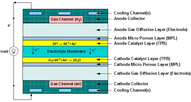
Hydrogen flows into the fuel cell on the anode side. It diffuses through the porous gas diffusion layer (GDL) and micro-porous layer (MPL), which is optional for the operation of a PEMFC, and then comes in contact with the catalyst layer. Here it forms hydrogen ions and electrons. The hydrogen ions diffuse through the polymer electrolyte membrane at the center, the electrons flow through the gas diffusion layer to the current collectors and into the electric load attached. Electrons enter the cathode side through the current collectors and the gas diffusion layer. Similarly, oxygen (or air) flows into the fuel cell on the cathode side and diffuses through the porous gas diffusion layer and then micro-porous layer to reach the catalyst layer. At the catalyst layer, the electrons, the hydrogen ions, and the oxygen combine to form water.
In the PEMFC model in Ansys Fluent, two electric potential fields are solved. One potential is solved in the membrane and the catalyst layer. The other is solved in the TPB catalyst layer, the micro-porous layer, the porous electrode, and the current collectors. The rates of electrochemical reactions are computed in the TPB layers at both the anode and the cathode. Based on the cell voltage that you prescribe, the current density value is computed. Alternatively, a cell voltage can be computed based on a prescribed average current density.
The polymer electrolyte membrane fuel cell (PEMFC) has emerged as a favored technology for auto transportation and power generation because it is compact, clean, runs at low temperature (<100° C), permits an adjustable power output, and can be started relatively rapidly. Hydrogen is supplied at the anode and air is supplied at the cathode. The following electrochemical reactions take place in the anode and cathode triple phase boundary (TPB) layers, respectively,
 | (20–1) |
 | (20–2) |
Electrons produced in the anode travel through an external circuit to the cathode, while
protons ( ) travel through the membrane from the anode TPB to the cathode TPB, thereby
forming an electrical circuit.
) travel through the membrane from the anode TPB to the cathode TPB, thereby
forming an electrical circuit.
In a PEM fuel cell, the three phases of water are present. The gas and liquid water phases are present in all the physical domains except the solid membrane and current collectors. Water is also present in the dissolved phase, but only inside the catalyst layers and the membrane. The water produced by the cathode side electro-chemistry is assumed to be in the dissolved phase (Equation 20–2).