Traceability is a key feature of medini analyze. It is used to e.g.:
Relate entries in hazard lists to safety goals
Allocate safety requirements to elements in hardware or software architectures
Allocate software model elements to hardware elements
Relate events in the FTA models to elements in the software model or the hardware model
Relate FTA models or FMEA models to safety requirements or safety goals
Relate entries in the FMEA to the corresponding elements in the hardware model
Relate external documents to medini analyze model elements
Besides these kinds of trace relations, traces can be used for various purposes depending on the processes in which medini analyze is applied.
Traces can be established by:
the Quick Link feature between two elements in the Model Browser,
by the Trace Matrix for multiple elements at once,
directly on diagrams by drawing a trace relation,
by the traces tab in the property view of an element.
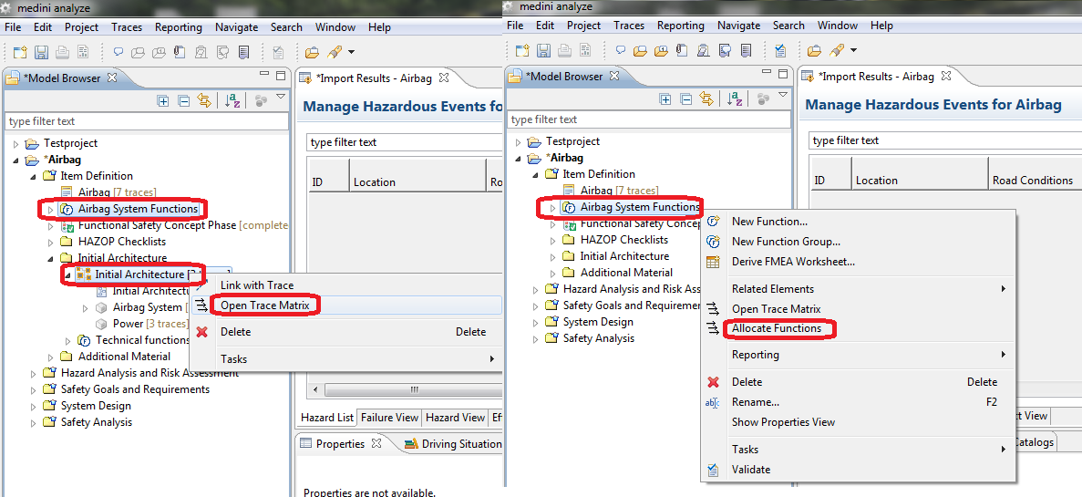
In addition, for selected activities a direct access to a trace matrix is also available by the "Allocate xxx" command from the context menus of packages in the Model Browser or from the main menu "Traces".
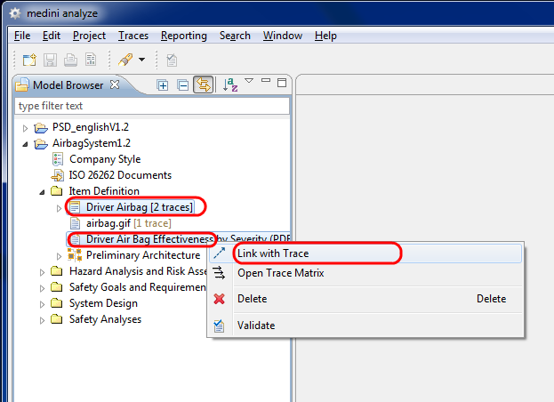
For a Quick-Link-trace select any two elements in the Model Browser (press the "Ctrl"-key when clicking on the second element). Afterwards, the "Link with Trace" has to be chosen from the context menu or from the main menu "Traces".
For the invocation of the trace matrix select one or two packages or models and choose "Open Trace Matrix" from the context menu of any of the selected packages resp. models or the main menu "Traces".
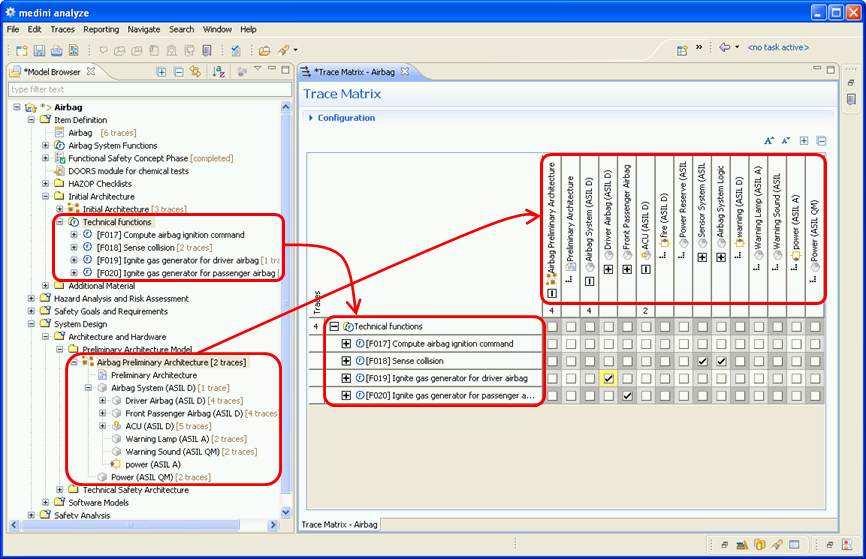
The elements contained in the selected packages or models are used as row resp. column header for the matrix.
For an easy comprehension of large trace matrices, the sub-structuring of elements will be kept in the trace matrix. When clicking on the "+"-symbol of a structured element it will unfold its structure and add additional rows resp. columns to the matrix; clicking on the "-"-symbol of such an unfolded element will fold it again.
Clicking into a cell creates a trace between the element corresponding to the row and the element corresponding to the column of that cell. The existence of such a trace will be indicated by a tick-mark. Clicking into such a marked cell will on the other side remove the trace between the two elements (and also the tick-mark).
Please note trace creation is not transitive: creation of a trace to a sub-structured element will not automatically create traces to all its contained elements!
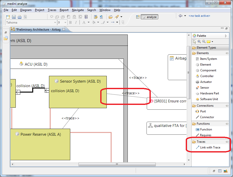
Traces can also be added between elements that are shown on a diagram. In order to do so, the trace relation has to be selected from the diagram editor palette and drawn between the diagram elements that should be connected.
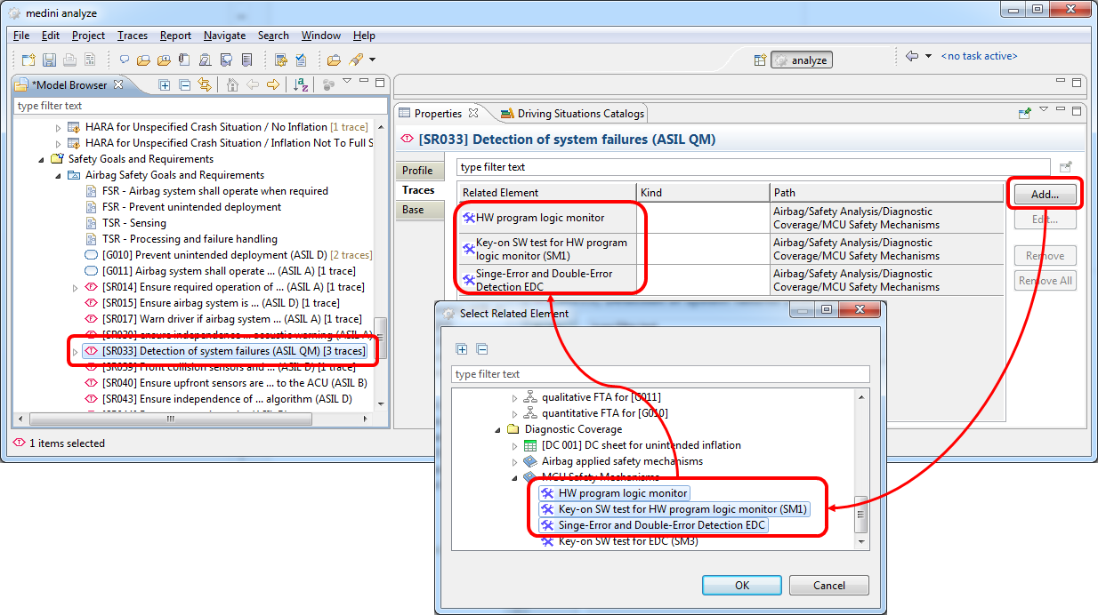
The property view of each element in the model browser has a tab for the traces of the element. The property view can be opened by the context menu "Show Property View" or via the main menu "Window->Show View ->Properties". In order to create a trace, the trace tab in the property view has to be selected and the "Add" button has to be pressed. In the upcoming selection dialog, one or more elements have to be selected as target of the trace.
Please note: the "OK" button in the element selection dialog is only enabled, if elements are selected for which traces are currently not existing (i.e. to which a new trace can be established.)
For better visibility the number of traces of an element is indicated in the Model Browser (cp. label decoration). Additionally, the matrix indicates the number of traces to child elements in an extra header row/column on each axis. This helps to locate traces deeper down in the hierarchy that are not immediately visible. Note that this number might differ from the number of traces in the model browser, since only those traces of nested elements are counted which point to elements on the other axis!
Traces can be edited, i.e. it is possible to change the source and target end of a trace and keep its properties.
This can be done either on a graphical editor (redirecting the trace) or by using trace tab in the property view of an element and pressing the "Edit..." button for a particular trace that is visualized. After pressing the "Edit..." button, an element selection dialog is shown. For further details see Creation of traces.
Similar to their creation, there are also different ways to delete traces between elements:
the "Unlink Traced Elements" action between two elements in the Model Browser,
by the Trace Matrix for multiple elements at once,
directly on diagrams by removing a trace relation,
by the traces tab in the property view of an element.
To delete just a single trace between two elements select the elements and choose "Unlink traced Elements" from the context menu (this entry is only shown in case a trace exists between the elements).
If you want to delete multiple traces between elements of two packages select the models or packages and open the trace matrix. You can now click into any marked cell in order to remove the trace between the elements corresponding to row and column of that cell.
On a diagram, trace relations can be selected and deleted as other relations between diagram elements - using the "Del" key or the "Delete from Model..." context menu actions.
When opening the property view of an element, traces shown in the trace tab can be deleted via the "Remove" button. All traces can be removed by the "Remove All" button.
Dangling traces are traces for which at least one of the elements that are connected does not exist any more while the trace itself is still part of the model. A potential source of a dangling trace is the teamwork, i.e. when two models are changed in parallel. The tool does not automatically delete these dangling traces, as you might want to see them to base decisions on this knowledge.
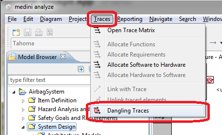
To find out about dangling traces, the main menu "Traces-> Dangling Traces" can be used.
In the following dialog, all dangling traces with their traced elements (if available) are shown.
The dangling trace detection is searching for dangling traces in the selected element and its contained elements only. To detect all dangling traces for a whole project, the project itself should be selected in the model browser.
In case that an element at the end of a trace is not in the model, the string "(unknown)" is shown.
It is possible to select one or more dangling traces and delete them. Multiple selection (using the "Ctrl." key) to delete multiple dangling traces at once is supported. It is also possible to use "Ctrl. A" to select all dangling traces and delete them at once.
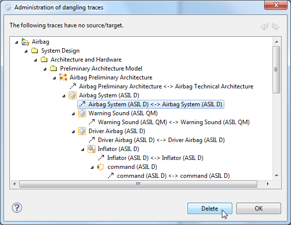
The two arrows on the top right side of the dialog are used for Undo and Redo of deletions of dangling traces.
By default the trace matrix shows in its rows and columns all model elements of the two selected packages. For large and complex models this may also result in a large trace matrix. Moreover, there may be a number of model elements shown in the trace matrix which are currently not of concern for you. In order to overcome these issues you may configure the trace matrix by filters. The configuration area is opened by clicking on "Configuration" on top of the trace matrix.
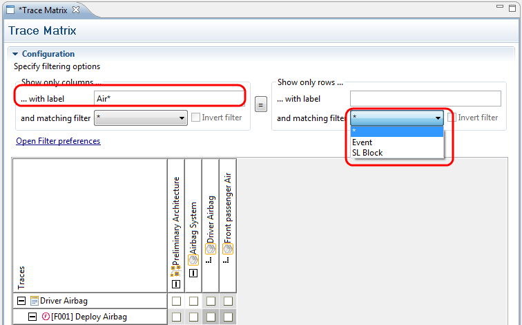
Filters can be defined independently for the columns and rows of the trace matrix. In case the same filter shall be applied for both, you may just specify a column filter and activate it for the rows too by clicking on the "="- button in the center.
Filtering options are given by a pattern for the labels of the matrix entries and/or by an application of a predefined filter.
The label pattern consists of a sequence of characters and will match all labels which contain words starting with the same sequence of characters.
Please note that this matching slightly differs from the matching in Search (Searching) where only labels exactly matching the search pattern will be shown.
The wildcard symbols "*" and "?" have a special meaning in the label pattern:
"*" corresponds to a sequence of zero or more arbitrary characters
"?" corresponds to exactly one arbitrary character.
Using the character "\" in front of a wildcard character, its special meaning can be suppressed.
Predefined filters can be applied in conjunction or instead of a label filter. Just click on the drop-down list and choose the appropriate predefined filter from the list. The trace matrix will now show all entries matching the label filter (if given) and the selected predefined filter. Use the "Invert filter" option to negate the application of the predefined filter.
Please note if the entries in the trace matrix are hierarchically organized, a filter application will show besides all entries matching the filter settings also all of their containing entries.
In order to use a predefined filter in the trace matrix configuration it has to be defined beforehand according to your needs. The filter definition wizard can be opened by either clicking on the "Open Filter preferences" link in the Trace matrix configuration or by opening the medini analyze preferences window (Window->Preferences) and selecting "Trace Matrix Filters".
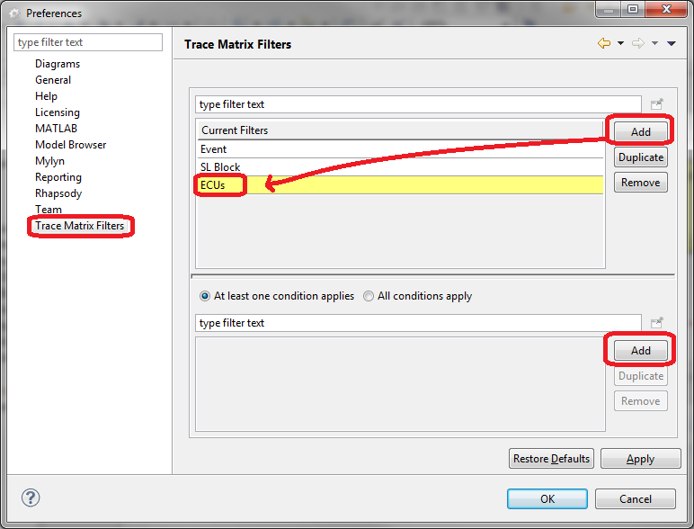
In the top part of the Preferences the table of currently defined filters is shown. Using "Add" and "Delete" a new filter can be defined resp. an existing filter can be removed. After creating a new filter a descriptive name should be provided for it.
The lower table shows the components of the selected filter. Each component consists of three entries:
component-kind: either "type" or "label"
matching condition: either "is" or "is not" (can be selected by clicking on the entry)
matching pattern: either a character sequence or a model element type name.
New components are added to a filter by clicking on the "Add"-button on the right side of the component table. When doing so, the tool asks first to select the kind of the component ("type" or "label"). After clicking on OK a new row will appear in the component table. To complete the definition you have to select now the appropriate matching condition and matching pattern.
In case of a label-filter you can directly type in the required pattern in the third column (in the same style as the label pattern described in the previous section). In case of a type-filter you have to select the desired type from the drop-down list in the third column of the table.
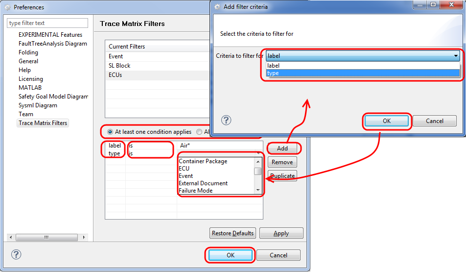
Using the radio buttons on top of the filter component table you may decide how the single components of a filter shall be combined.
After clicking on "Apply" and closing the Preferences window the newly defined filter will be available for the Trace matrix configuration.
A report can be generated for the trace matrix. In order to generate the report, open the trace matrix and press the "Generate a report from the table (Ctrl-R)" button in the tool bar of medini analyze. The report wizard will open. See Reporting and Document Generation for details on generating reports.
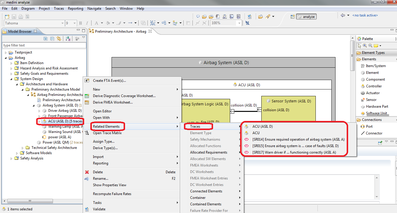
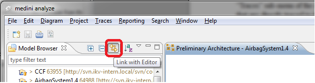
The traces can be used to navigate between the elements that are connected by a trace. In the "Related elements -> Traces" sub-menu of the context menu of any element in the Model Browser the list of all elements that are directly traced to it is shown. Selecting an entry from the list will select and highlight that traced element in the Model Browser. This way you can easily jump to related elements.
Note, that with enabling the "Link with Editor" button in the Model Browser, the corresponding editor (if one is open) will be activated and the element is highlighted in the editor.
Note, the navigation via traces is also available from the context menu of selected elements in the graphical and table editors. However, the selection and highlighting of the traced target element will always be done in the Model Browser.