The Soil Interaction property dialog is composed of 2 tabs as shown in the table below.
Figure 12.171: Tabs in the Soil Interaction property dialog
| Name of tab | Description |
| Characteristic |
This tab includes below items. 1. Dynamic sinkage 2. Normal pressure 3. Shear pressure |
| Geometry |
This tab includes below items. 1. Base geometry and vertical direction 2. Action geometry list and shape data |
The Characteristic tab is composed as follows.
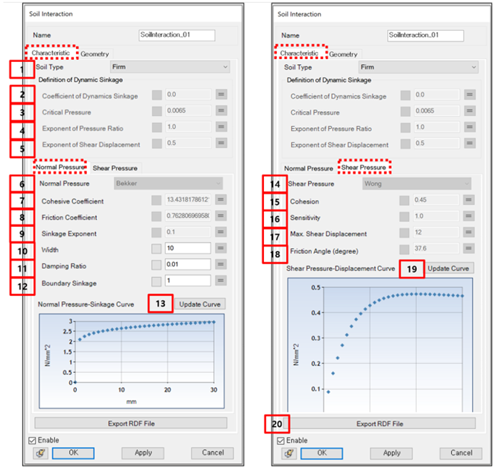
Figure 12.173: Description of Characteristic tab
| Parameter | Symbol | Description | Dimension (Range) |
| 1. Soil Type | N/A | Use to define the soil type. Firm, Clayey, Mud, User Defined, and so on are supported. When this is "User Defined", the input fields of all parameters are available. | N/A |
| 2. Coefficient of Dynamics Sinkage |  . . | Use to define the slope of dynamics sinkage for shear displacement. |
N/A (Real >= 0) |
| 3. Critical Pressure |  . . | Use to define the critical pressure for full collapse of soil. |
Force/Length^2 (Real > 0) |
| 4. Exponent of Pressure Ratio |  . . | Use to define the exponent for the pressure ratio. |
N/A (Real >= 0) |
| 5. Exponent of Shear Displacement |  . . | Use to define the exponent for the shear displacement ratio. |
N/A (Real >= 0) |
| 6. Normal Pressure | N/A | Use to define the formulation type for the normal pressure.
Bekker is only supported. | N/A |
| 7. Cohesive Coefficient |  . . | Use to define the cohesive coefficient of terrain deformation. |
Force/Length (Real >= 0) |
| 8. Frictional Coefficient |
| Use to define the frictional coefficient of terrain deformation. |
Force/Length (Real >= 0) |
| 9. Sinkage Exponent |  | Use to define the exponent for the sinkage. |
N/A (Real >= 0) |
| 10. Width | w | Use to defined the width of test track link. |
Length (Real > 0) |
| 11. Damping Ratio | c* | Use to define the damping force for the normal force. |
N/A (Real >= 0) |
| 12. Boundary Sinkage | Δb | Use to set the boundary sinkage as shown in the figure below: 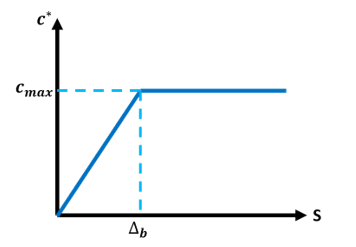 Damping force is calculated using the damping term of the contact force. The Damping Ratio (above) is multiplied by the stiffness value and used to calculate the damping coefficient. Boundary Sinkage is used to mitigate the effects of the damping forces: If
Else
where,
|
Length (Real > 0) |
| 13. Update Curve in Normal Pressure | N/A |
Use to draw the graph of normal pressure for sinkage.
The normal pressure can be calculated from Bekker's equation as follows.
| A |
| 14. Shear Pressure | N/A | Use to define the formulation type for shear pressure. Only
Wong type is available. | N/A |
| 15. Cohesion | C | Use to define the cohesion of soil. | Force/Length^2 |
| 16. Sensitivity |  . . | Use to define the sensitivity of soil. |
N/A (Real > 0) |
| 17. Max. Shear Displacement |  . . | Use to define the shear displacement at the maximum shear stress. |
Length (Real > 0) |
| 18. Friction Angle (degree) |
| Use to define the friction angle. |
Degree (90 > Real >= 0) |
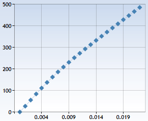
| 19. Update Curve in Shear Pressure | N/A |
Use to draw the graph of normal pressure for sinkage.
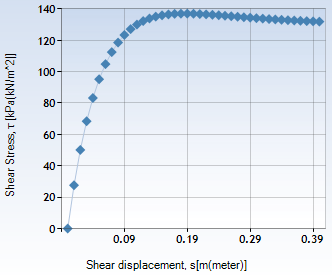
The shear pressure can be calculated from Wong's equation as follows.
here, P is the instantaneous value of the normal load. | N/A |
| 20. Export RDF File | N/A | Use to export the RDF file for the standalone solver. | N/A |


The Geometry tab is composed as follows.
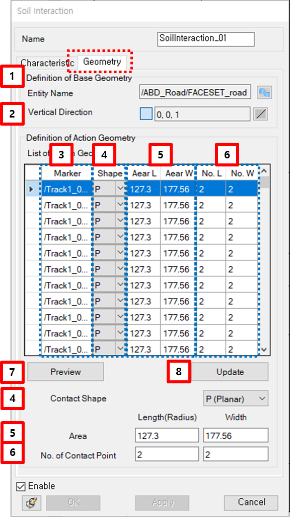
Figure 12.175: Description of Geometry tab
| Parameter | Symbol | Description | Dimension (Range) |
| 1. Definition of Base Geometry | N/A | Use to set base geometry. The candidate is Faceset entity. | N/A |
| 2. Vertical Direction |  . . | Use to set the nominal vertical direction of road with the direction picker. The orientation of geometry reference frame of road is determined with the specified direction. | N/A |
| 3. List of Marker | N/A | Use to show the parameters of contact geometry for each marker. When lines are selected, they can be removed through the "Remove" button or their parameters will be updated through the "Update" button. You can add the markers through the "Add" button. | N/A |
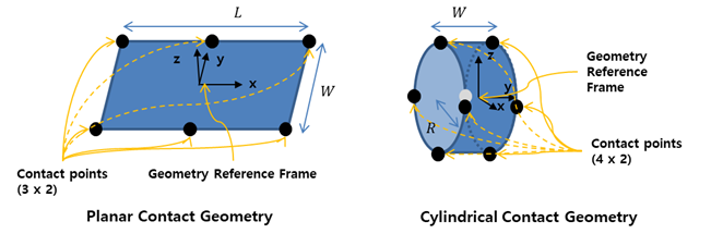
| 4. Contact Shape | N/A | Use to define the type of contact shape. Two types of "Planar" and "Cylindrical" are available. | N/A |
| 5. Contact Area |
| Use to define the sizes of the contact geometry. Refer the contact geometry for more information. |
Length (Real>0) |
| 6. No. of Contact Point | N/A | Use to define the number of the contact points. Refer the contact geometry for more information. |
N/A (Integer>1) |
| 7. Preview | N/A | Use to display contact point. | N/A |
| 8. Update | N/A | Use to set the parameters of the selected markers in the list of marker. | N/A |