


Force parameters are defined in the Tire property dialog as shown in the figure and table below.
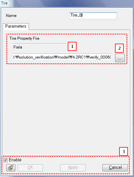
Figure 6.55: Description of parameters in the Tire property dialog
| Parameter | Symbol | Description | Dimension (Range) |
| 1. Type | N/A | Displays the tire force type defined in the Tire Property File (*.tir). | N/A |
| 2. TIR file | N/A | Use to select a TIR file. | N/A |
| 3. Control buttons | N/A | If all necessary parameters are set, these buttons are enabled. For more information about the control buttons, refer to Entity Properties Access and Modification. | N/A |
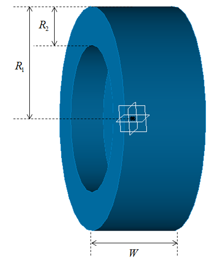
The graphics of the wheel body can be represented as shown in the figure below.
Wheel body parameters are defined in the Body property dialog as shown in the figures and table below.
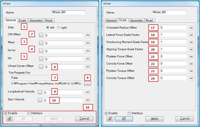
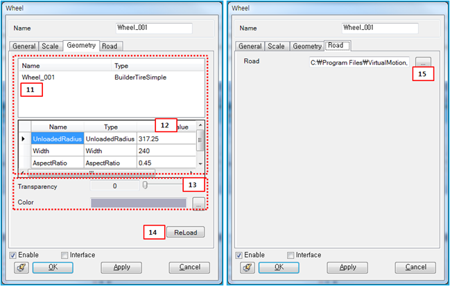
Figure 6.59: Description of parameters in the Wheel body property dialog
| Parameter | Symbol | Description | Dimension (Range) |
| 1. Side | N/A | Use to select or to specify the attached location of tire. | N/A |
| 2. CM Offset |
 | Use to set an offset from the position of the tire marker to the position of the CM of wheel body in the lateral (spin) direction. |
Length (Real) |
| 3. Mass |
 | Use to set the mass of the wheel body. |
Mass (Real > 0) |
| 4. Ixx Iyy |  , , | Use to set the mass moment of inertia of the wheel body in the longitudinal and vertical directions. |
Mass*Length^2 (Real > 0) |
| 5. Izz |
 | Use to set the mass moment of inertia of the wheel body in the lateral (spin) direction. |
Mass*Length^2 (Real > 0) |
| 6. Wheel Center Offset |
 | Use to set an offset from the position of the tire marker to the center position of wheel graphic in the lateral (spin) direction. |
Length (Real) |
| 7. Type | N/A | Displays the tire force type defined in the Tire Property File (*.tir). | N/A |
| 8. TIR file | N/A | Use to select a Tire Property File (*.tir). | N/A |
| 9. Longitudinal Velocity |
 | Use to set the initial velocity of the wheel body in the longitudinal direction (x-axis). |
Length/Time (Real) |
| 10. Spin Velocity |
 | Use to set the initial angular velocity of the wheel body in the lateral direction (y-axis). |
Radian/Time (Real) |
| 11. Geometry | N/A | Display the name of the body and geometry type. | N/A |
| 12. Geometry Parameter |  , , , , | Displays the Unloaded Radius, Width, and Aspect Ratio defined in the TIR file. The tire graphics are determined from these parameters as shown in Figure 6.52: Tire creation dialog. | Length, Length, N/A |
| 13. Transparency and Color | N/A | Use to set the transparency and color of the wheel body. | N/A |
| 14. Reload | N/A | Use to reload the TIR file. If the geometry parameters are changed in the file, the changed wheel body will be displayed when clicking this button. | N/A |
| 15. Road | N/A | Use to select a Road Data File (*.rdf). | N/A |
| 16. Control buttons | N/A | If all necessary parameters are set, these buttons are enabled. For more information about the control buttons, refer to Entity Properties Access and Modification. | N/A |
| 17. Unload Radius Offset | N/A | Use to set a force offset due to the unloaded radius. |
Force (Real) |
| 18. Lateral Force Scale Factor | N/A | Use to set the scale factor for lateral force. |
N/A (Real) |
| 19. Overturning Moment Scale Factor | N/A | Use to set the scale factor for overturning moment. |
N/A (Real) |
| 20. Aligning Torque Scale Factor | N/A | Use to set the scale factor for aligning torque. |
N/A (Real) |
| 21. Plysteer Force Offset | N/A | Use to set a force offset due to the plysteer. |
Force (Real) |
| 22. Conicity Force Offset | N/A | Use to set a force offset due to the conicity. |
Force (Real) |
| 23. Plysteer Torque Offset | N/A | Use to set a torque offset due to the plysteer. |
Force (Real) |
| 24. Conicity Torque Offset | N/A | Use to set a torque offset due to the conicity. |
Force (Real) |