


RDF and TIR files are needed to create a tire force. The creation steps and definition of parameters are shown in the figure and table below. When creating the force, two markers and one wheel body are created simultaneously to represent the force.
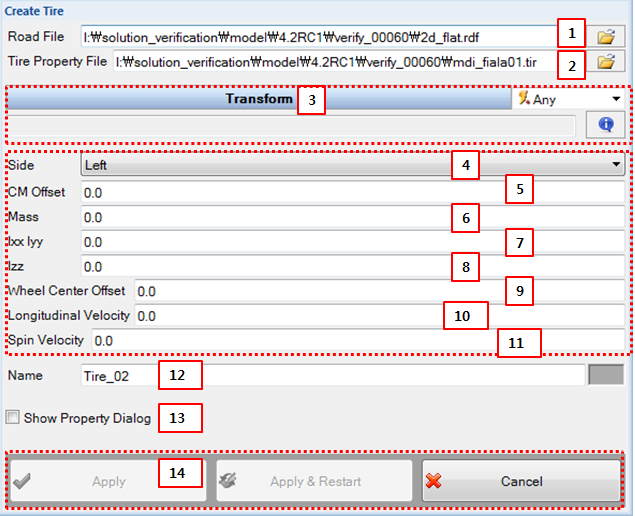
Figure 6.53: Description of parameters in the Tire creation dialog
| Parameter | Description |
| 1. Road File | Use to select a Road Data File (*.rdf). |
| 2. Tire Property File | Use to select a Tire Property File (*.tir). |
| 3. Transform | Use to set the position and orientation of the tire marker. |
| 4. Side | Select either or to specify the attached location of the tire. |
| 5. CM Offset | Use to set an offset from the position of the tire marker to the position of the CM of wheel body in the lateral (spin) direction. |
| 6. Mass | Use to set the mass of the wheel body. |
| 7. Ixx Iyy | Use to set the mass moment of inertia of the wheel body in the longitudinal and vertical directions. |
| 8. Izz | Use to set the mass moment of inertia of the wheel body in the lateral (spin) direction. |
| 9. Wheel Center Offset | Use to set an offset from the position of the tire marker to the center position of wheel graphic in the lateral (spin) direction. |
| 10. Longitudinal velocity | Use to set an initial velocity of the wheel body in the longitudinal direction (x-axis). |
| 11. Spin velocity | Use to set an initial angular velocity of the wheel body in the lateral direction (y-axis). |
| 12. Name | Use to set the name of the Tire object. The name of the rigid body is set as default. If you want to modify the name, you must change the name in the property dialog of the body. |
| 13. Show Property Dialog | Use to open the property dialog after finishing the creation operation. |
| 14. Control buttons | If all necessary parameters are set, these buttons are enabled. For more information about the control buttons, refer to Entity Creation. |