


Geometry properties such as the base and action contact surfaces are defined in the Tie contact property dialog. The parameters on the Tie tab are as shown in the figure and table below.
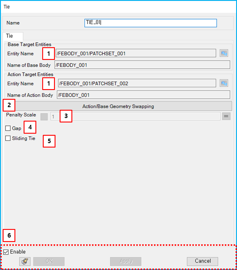
Figure 7.21: Description of parameters on the Tie tab
| Parameter | Symbol | Description | Dimension (Range) |
| 1. Entity Name | N/A | Use to set the base or action geometry. A Patchset or Edgeset can be selected using the Faceset Picker. | N/A |
| 2. Action/Base Geometry Swapping | N/A | Use to exchange action and base geometries for one another. If the base surface includes more action nodes, Tie contact will give a more reliable solution. | N/A |
| 3. Penalty Scale | N/A | Use to set the scale of the penalty which is used to calculate the constrained force. | N/A (Real>0.0) |
| 4. Gap | N/A | Use to consider the gap between two Patchsets or Edgesets. When this option is selected and the action node has a displacement along the base surface, the constrained force is not applied to the action node. | N/A |
| 5. Sliding Tie | N/A | Use to release the constraint for the tangential direction of the base geometry. | |
| 6. Control buttons | N/A | If all necessary parameters are set, these buttons are enabled. For more information about the control buttons, refer to Entity Properties Access and Modification. | N/A |