


From the Nodeset properties dialog, the nodes and its parameters can be displayed and modified as shown in the figure and table below.
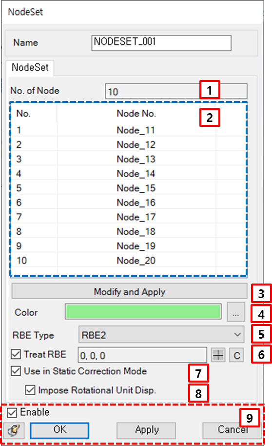
Figure 3.166: Parameters in the Nodeset properties dialog
| Parameter | Symbol | Description | Dimension (Range) |
| 1. No. of Node | N/A | Displays the number of nodes in the Nodeset. | N/A |
| 2. List of Node | N/A | Displays the node IDs in the Nodeset. | N/A |
| 3. Modify… | N/A | Use to add or remove the nodes by using the MultiNode Picker. | N/A |
| 4. Color | N/A | Use to set the color of the Nodeset. | N/A |
| 5. RBE Type | N/A | Use to set the RBE type, such as RBE2 or RBE3. RBE2 does not allow relative motion between dependent nodes, while RBE3 allows relative motion between dependent nodes by weighting of motion. | N/A |
| 6. Treat RBE | N/A | Use to set the option which treats the Nodeset as a rigid region. When this option is selected, the position of the master node can be defined by using the Point Picker or by clicking the C button to set the master node position that sets as the center of Nodeset. | N/A |
| 7. Use in Static Correction Mode | N/A | Use to set the interface node during body eigenvalue analysis. This option is enabled when the Treat RBE option is selected. When this option is selected, the master node is treated as the interface node which can be used as a connector for a Modal FE Body. | N/A |
| 8. Impose Rotational Unit Disp. | N/A |
This option is autoamtically selected when Use in Static Correction Mode (above) is selected. Clear this option to exclude the rotational mode of the master node for a Modal FE Body. | N/A |
| 9. Control buttons | N/A | If all necessary parameters are set, these buttons are enabled. For more information about the control buttons, refer to Entity Properties Access and Modification. | N/A |