


From the Boundary Condition property dialog, the parameters for the base marker, node set and constrained type can be modified as shown in the figure and table below.
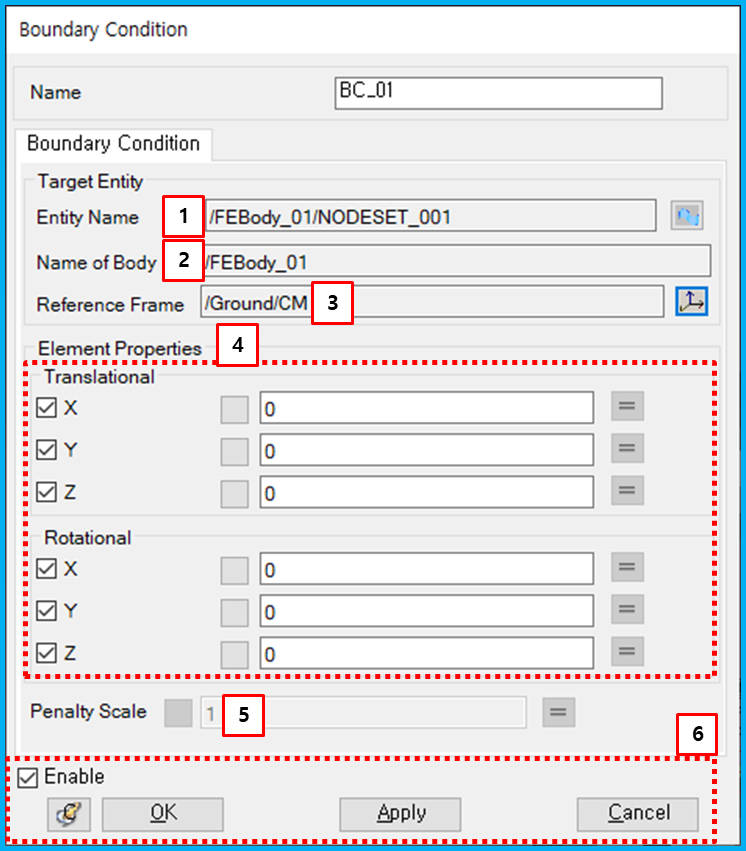
Figure 5.77: Description of parameters in the Boundary Condition property dialog
| Parameter | Symbol | Description | Dimension (Range) |
| 1. Entity Name | N/A | Use to select the Nodeset using the General Picker. | N/A |
| 2. Name of Body | N/A | Use to show the parent body name of the selected Nodeset. | N/A |
| 3. Reference Frame | N/A | Use to set the reference marker using the General Picker. | N/A |
| 4. Translational and Rotational | N/A | Use to set the constrained direction by using the check boxes, and use to set the constrained displacement value by using text boxes. | N/A |
| 5. Penalty Scale | N/A | Use to set the scale of penalty which is used to calculate the constrained force. | N/A (Real>0.0) |
| 6. Control buttons | N/A | If all necessary parameters are set, these buttons are enabled. For more information about the control buttons, refer to Entity Properties Access and Modification. | N/A |