


Connecting properties such as the base and action bodies and the locations on the bodies are defined in the Distance Joint creation dialog as shown in the figure and table below. When creating the joint, two markers are simultaneously created to represent the joint. The distance can be determined by defining two locations on the bodies. The orientations of the two markers are created according to the identity matrices.
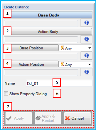
Figure 5.55: Description of parameters in the Distance Joint creation dialog
| Parameter | Description |
| 1. Base Body | Use to set the base body using the General Picker. This defines the parent body of the base marker. |
| 2. Action Body | Use to set the action body using the General Picker. This defines the parent body of the action marker. |
| 3. Base Position | Use to set the location on the base body using the Point Picker. This defines the position of the base marker. |
| 4. Action Position | Use to set the location on the action body using the Point Picker. This defines the position of the action marker. |
| 5. Name | Use to set a name for the Distance Joint. |
| 6. Show Property Dialog | Use to open the property dialog after finishing the creation operation. |
| 7. Control buttons | If all necessary parameters are set, these buttons are enabled. For more information about the control buttons, refer to Entity Creation. |