


A Curveset can be accessed from the Body category on the ribbon menu for a subsystem or part. There are two ways to create a Curveset as shown in the figures below. When the option is used, a Curveset can be created by selecting edges on a solid body by using the MultiEdge Picker (Rigid Body) as shown in the figure below and in the following table. When the option is used, a text file which contains position vectors must be defined.
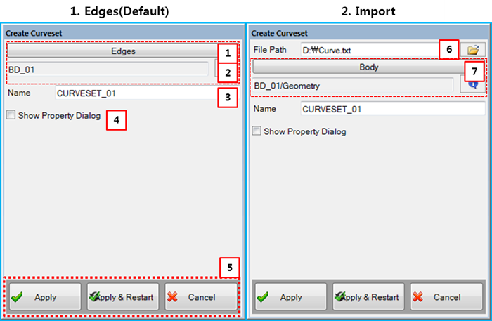
Figure 3.67: Description of parameters in the Create Curveset dialog
| Parameter | Description |
| 1. Edges | Use to set the edges of the Curveset using the MultiEdge Picker (Rigid Body). The edges must belong to the same body. |
| 2. Information | Used to display the name of body to which the Curveset edges belong. |
| 3. Name | Use to set the name of the Curveset. |
| 4. Show Property Dialog | Use to open the properties dialog after finishing the creation operation. |
| 5. Control buttons | If all necessary parameters are set, these buttons are enabled. For more information about the control buttons, refer to Entity Creation. |
| 6. File Path | Use to set a file for the points. The file contains position vectors as shown in Figure 4.16: File format for Beam Group. |
| 7. Body | Use to set a parent body for an imported Curveset. |