


Connecting properties such as the base and action bodies, and the location, the two spin axes and reference direction on the bodies are defined in the Constant Velocity Joint creation dialog as shown in the figure and table below. When creating the joint, two markers are simultaneously created to represent the joint. The z-axes of the markers are defined as the rotational directions. The x-axes of the markers which is defined as the orthogonal axis must be same to ensure the relative angle between two markers is initially zero. The other axes of the markers are determined by the right hand rule.
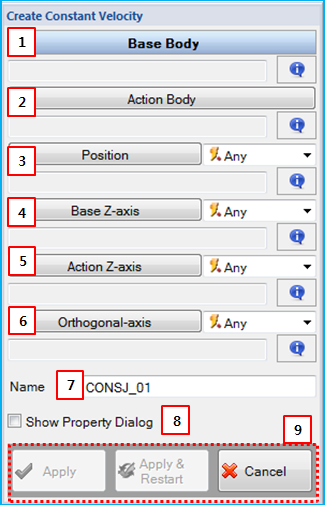
Figure 5.63: Description of parameters in the Constant Velocity Joint creation dialog
| Parameter | Description |
| 1. Base Body | Use to set the base body using the General Picker. This defines the parent body of the base marker. |
| 2. Action Body | Use to set the action body using the General Picker. This defines the parent body of the action marker. |
| 3. Position | Use to set the location on the base and action bodies by the Point Picker. This defines a position of the base and action markers. |
| 4. Base Z-axis | Use to set the spin axis on the base body using the Direction Picker. This defines the z-axis of the base marker. |
| 5. Action Z-axis | Use to set the spin axis on the action body using the Direction Picker. This defines the z-axis of the action marker. |
| 6. Orthogonal-axis | Use to set the reference direction by the Direction Picker. This defines the x-axes of the base and action markers. The axis must be orthogonal to the pre-defined z-axes. |
| 7. Name | Use to set the name of Constant Velocity Joint. |
| 8. Show Property Dialog | Use to open the property dialog after finishing the creation operation. |
| 9. Control buttons | If all necessary parameters are set, these buttons are enabled. For more information about the control buttons, refer to Entity Creation. |