The Shaft Set and housing are connected by a bearing, so the bearing outer raceway and inner raceway must be matched to an accurate position. The bearing position is therefore shown in the Assembly tab, along with the Reference Body and the Reference Vector.
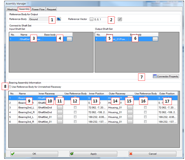
Figure 14.280: Parameters in Assembly tab
| Parameters | Description |
| 1. Reference Body | Use to set the reference body. If you want to set the gear box characteristic on a moving part such as a moving car, you must set the moving body as the reference body. |
| 2. Reference Vector | Use to set the reference vector. The reference vector is used for the output formulation. |
| 3. Input Shaft Set | Lists all of the input Shaft Sets. |
| 4. Base body(input) | Use to set the base body of the input Shaft Set. If the base body of the input shaft and the base body of the output shaft are different, that body can be selected here. |
| 5. Output Shaft Set | Lists all of the output Shaft Sets. |
| 6. Base body(output) | Use to set the base body of the output Shaft Set. If the base body of the input shaft and the base body of the output shaft are different, that body can be selected here. |
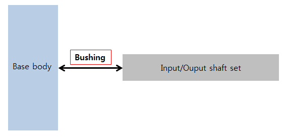
| 7. Connector property | Use to set the connector parameters (bushing). Refer to the connector topology in Figure 6.25: Description of parameters in the Bushing property dialog. |
| 8. Use Reference Body for Unmatched Raceway | Use to set the reference body for the unmatched raceway. If the inner raceway or the outer raceway is not set to the Shaft Set, the bearing model is not generated in the simulation. In this case, the unset raceway can be set to the reference body. |
| 9. Name (Bearing) | Show the bearing name. |
| 10. Inner Raceway | Show the inner raceway which is included to the Shaft Set or housing. |
| 11. Select Base Body(inner) | Use to set the base body of the inner raceway. |
| 12. Use Reference Body(inner) | Use to set the reference body as a base body. |
| 13. Inner Position | Show the inner raceway position in the global reference frame. |
| 14. Outer Raceway | Show the outer raceway which is included to the Shaft Set or housing. |
| 15. Select Base Body(outer) | Use to set the base body of the outer raceway. |
| 16. Use Reference Body(outer) | Use to set the reference body as a base body. |
| 17. Outer Position | Show the outer raceway position in the global reference frame. |