


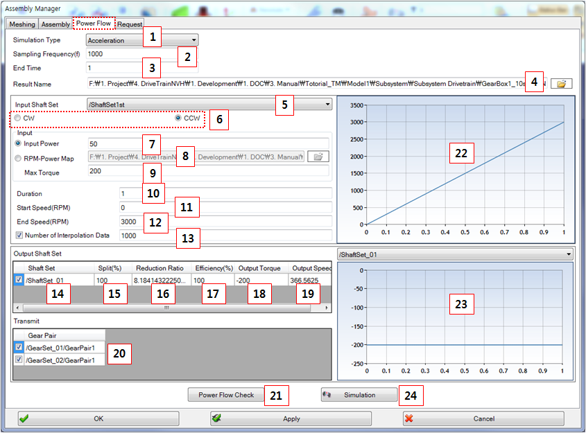
Figure 14.283: Parameters in the Assembly Manager Power Flow tab
| Parameters | Description |
Dimension (Range) |
| 1. Simulation Type |
Use to set the simulation type: - Acceleration - Deceleration - User Input | N/A |
| 2. Sampling Frequency |
Use to set the sampling frequency which is set to the maximum step size as follows.
| Frequency |
| 3. End time | Use to set the ending time. | Time(s) |
| 4. Result Name | Use to set the result name and the path. | N/A |
| 5. Input Shaft Set | Use to select the input Shaft Set. | N/A |
| 6. Rotating direction | Use to set the rotation direction of the input Shaft Set. If is selected, the sign of the rotational direction is negative with respect to the Shaft Set direction. If is selected, the sign of the rotational direction is positive. | N/A |
| 7. Input Power | Use to set the input power. | Power (Kw) |
| 8. RPM-Power Map | Use to set the RPM-Power map. A simulation scenario can be used as the map by using this option. | N/A |
| 9. Max Torque | Use to set the maximum torque | Torque(Nm) |
| 10. Duration | Use to set the duration of the acceleration or deceleration. | Time(s) |
| 11. Start Speed(RPM) | Use to set the starting rpm. | Angular velocity(RPM) |
| 12. End Speed(RPM) | Use to set the ending rpm. | Angular velocity(RPM) |
| 13. Number of Interpolation data | Use to set the number of interpolated data. The input motion is created by the spline. If the input speed varies, this value is very important. | N/A |
| 14. Output Shaft Set | Use to set the output Shaft Set. At least one output Shaft Set must be selected. | N/A |
| 15. Split (%) | Use to set the power-ssplit percentage. The sum of percentages must be 100. | Percentage(%) |
| 16. Reduction Ratio | Show the final reduction ratio. If you do not define an output load, you can input a value directly and this could be used during the power flow check. | N/A |
| 17. Efficiency (%) | Use to set the efficiency percentage. | Percentage(%) |
| 18. Output Torque | Show the output torque at output Shaft Set. | Torque(Nm) |
| 19. Output Speed | Show the calculated output speed. | Angular velocity(RPM) |
| 20. Transmit | Use to select the gear set to engage. If a gear set is not selected, there is no gear meshing during the simulation. | N/A |
| 21. Power Flow Check | Use to calculate the power flow. | N/A |
| 22. Input motion | Show the final input motion which considers all related parameters. Input motion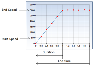 | N/A |
| 23. Output Torque(Chart) | Show the final output torque which considered all related parameters. | N/A |
| 24. Simulation | Use to run the Motion Solver. | N/A |

The power and torque are calculated as follows:
 | (14–65) |
 | (14–66) |