The geometry of the hemispherical and flat rings was created in DesignModeler.
After attaching the geometry, open the Geometry properties from the project schematic and change the Analysis Type to 2D under Advanced Geometry Options, as shown in the following image.
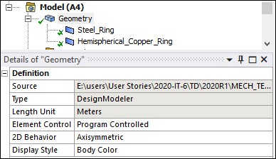
In the Mechanical Application, you can change the 2D behavior to axisymmetric in the Details panel of the Geometry object as shown in the following image.
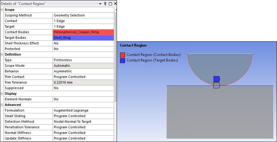
The rings are meshed with 2D axisymmetric elements (PLANE182 with KEYOPT(3) = 1). Frictionless contact is modeled between the two rings by overlaying the surfaces with contact and target elements (CONTA172 and TARGE169).
The contact settings for this model are shown in the following image. The model uses asymmetric contact to simulate wear on the top hemispherical ring: contact elements are defined on the top ring and target elements are defined on the bottom ring.
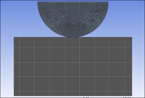
A global element size of 1 mm is used for meshing. Local mesh sizing is also defined. For the steel ring, Number of Divisions = 70 on the horizontal edges and Number of Divisions = 35 on the vertical edges. For the hemispherical copper ring, Number of Divisions = 60 on the curved edge and Number of Divisions = 40 on the flat edge . The meshed model is shown below.
Workbench does not have an option for modeling the Archard wear model. Therefore, a command snippet is used to incorporate this model. For information on adding command snippets in Mechanical, see Commands (APDL).
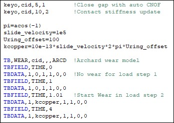
In the first part of this command input, element key options are set to control certain contact behaviors. KEYOPT(5) = 1 is set to close the gap with an auto contact surface offset (CNOF). KEYOPT(10) = 2 is set to perform a contact stiffness update each iteration so that the actual elastic slip never exceeds the maximum allowable limit (SLTO) during the entire solution. (For more information on the KEYOPTs and the real constants CNOF and SLTO, see the CONTA172 element description.)
Contact elements are defined on the surface undergoing wear. The Archard wear
model is defined by the
TB,WEAR,MATID,,,ARCD command, and the
wear model is associated with the contact elements through the
MATID (cid) specified on
TB,WEAR.
The Archard wear model is specified by inputting constants C1 through C4 on the TBDATA command. These constants represent the wear coefficient (K), material hardness (H), the contact pressure exponent (m), and the sliding velocity exponent (n). (See Archard Wear Model for more information.)
The wear coefficient K can sometimes be scaled to simplify modeling. As an example, consider this ring-on-ring problem in which the rings are rotating at constant speed. The only effect of this rotation/sliding at the contact surface is to produce wear (friction is absent). The wear coefficient K can be scaled such that the rotation is not explicitly modeled, but its effect is included in the computation of wear. This greatly reduces the simulation time and effort.
More specifically, if a linear dependence of wear rate on the sliding velocity is assumed, the wear coefficient K can be scaled by the sliding velocity. In this example, sliding velocity is 2πN*R, where N = 100,000 revolutions/sec and R is the distance from the axis of rotation. Scaling K by 2πN*R results in the wear rate being linearly dependent upon the sliding velocity without explicitly modeling the sliding. The distance from the axis of rotation (R) is assumed to be constant for all points and is taken as 100 mm (the distance of the center of the ring from the axis of rotation).
There are two approaches for modeling wear:
Wear on One Contact Surface (Asymmetric Contact)
Wear on Both Contact Surfaces (Symmetric Contact)
This example only considers the first approach.
Wear on One Contact Surface (Asymmetric Contact)
Asymmetric contact is used to model wear in the hemispherical copper ring only. For this case, contact elements are defined on the copper ring while target elements are defined on the steel ring. The Archard wear model is defined as a material associated with the contact elements. The material data for wear is defined using TBDATA commands. The wear properties for the copper ring are as follows:
| Wear Properties for the Copper Ring | ||
| Property | TBDATA Constant | Value |
| Wear Coefficient (K) | C1 | kcopper = 10e-13*2π*1e5*100 (scaled by sliding velocity 2πN*R) |
| Hardness (H) | C2 | 1 MPa |
| Pressure exponent (n) | C3 | 1 |
| Velocity Exponent (m) | C4 | 0 |
To initiate wear after a steady state has been reached with respect to loading, TB,WEAR is used in conjunction with TBFIELD,TIME. The problem is simulated in two load steps. In the first load step, pressure is ramped to the desired level and wear is inactive. In the second load step, the pressure is held constant and wear is activated.
Modeling wear involves repositioning contact surface nodes to simulate the material removal process. As a result, the element quality of the solid elements underlying the contact elements can quickly deteriorate. This examples uses the Nonlinear Mesh Adaptivity feature to alleviate this problem when simulating large amounts of wear.
A wear-based contact criterion triggers nonlinear mesh adaptivity whenever the mesh is distorted. The critical ratio between the amount of wear and the underlying solid element's height is user-defined. When the criterion is reached, nonlinear mesh adaptivity is triggered.
Nonlinear mesh adaptivity requires the following steps:
Create a component that contains the contact elements that are undergoing wear.
Issue the NLADAPTIVE command to trigger adaptivity based on a wear criterion.
The Mechanical Application does not have an option for specifying the contact criterion for the Nonlinear Adaptive Region feature. Therefore, to implement nonlinear mesh adaptivity in this example, the following command snippet is used:
In this case, adaptivity occurs whenever wear at any contact point exceeds 50% of the average height of the solid element underlying the contact element. Each time the criterion is reached, the analysis is stopped, the mesh quality is improved by morphing the mesh, history-dependent variables and boundary conditions are mapped, and the analysis is restarted with an improved mesh. This process is done automatically.


