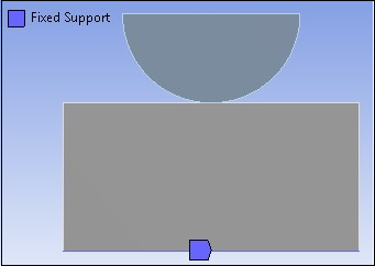
The bottom of the flat steel ring is fixed, as shown in the following image:
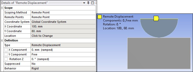
A remote point is inserted to define a rigid surface constraint between the nodes on the top surface of the hemispherical ring and a pilot node. The pilot node is constrained in the X direction and in rotation about the Z axis (using Remote Displacement scoped to Remote Point) as shown in the image below. The Remote Displacement behavior is set to Rigid.
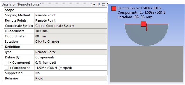
A remote force is applied on the remote point that is equivalent to a pressure of 4000 N/mm2. The equivalent pressure is ramped during the first load step from 0 to 4000 N/mm2 and is kept constant at 4000 N/mm2 during the second load step. Wear is activated in the second load step. Using the below formula, the calculated applied force is 150,796,320 N.
Fapplied = 4000 × pi × ((Uring_offset+Uring_R)2- (Uring_offset-Uring_R)2)
where:
| Uring_R = 30 mm |
| Uring_offset = 100 mm |