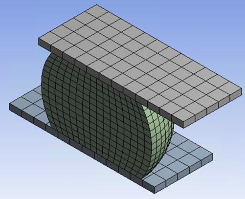
The geometry for the solder ball and copper plates was created in DesignModeler.
In the Workbench Project Schematic, insert a Coupled Field Transient analysis system and attach the geometry.
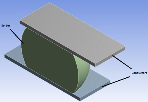
3D coupled-field elements (SOLID226) are used to model the solder ball and the conductors, and 3D surface-to-surface contact elements (CONTA174) are used to model contact between the solder ball and the copper conductors.
The following degrees of freedom (DOF) are needed for this analysis:
| Concentration (CONC) |
| Temperature (TEMP) |
| Voltage (VOLT) |
| Displacement (UX, UY, UZ) |
For the SOLID226 elements, KEYOPT(1) = 100111 activates these degrees of freedom. For the CONTA174 elements, KEYOPT(1) = 12 activates these degrees of freedom. (See the SOLID226 and CONTA174 element descriptions for more information on element KEYOPT settings).
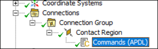
Because the diffusion and electric degrees of freedom are not available in the Mechanical user interface, Mechanical APDL commands are used to activate the required structural-thermal-electric-diffusion DOF:
These commands will be evident in subsequent command snippets.
Bonded contact (KEYOPT(12) = 5) is created between the solder and the conductors.
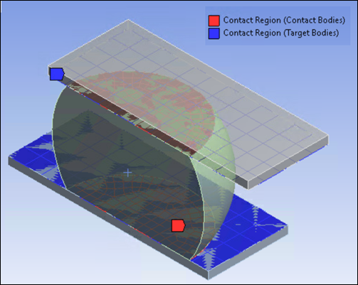
The Augmented Lagrange formulation is used along with the following contact properties:
| Contact Property | Contact Element Real Constant | Value |
| Structural stiffness | FKN | 1.0 times underlying element stiffness |
| Thermal conductance (pW/((μm)2*°C)) | TCC | 1E6 |
| Electrical conductance (pA/((μm)2*Volt)) | ECC | 1E14 |
| Diffusivity coefficient ((μm)3/s) | DCC | 1E6 |
Electrical conductance and diffusivity coefficient cannot be defined through the Mechanical user interface. Therefore, the contact properties are defined using a command snippet.
! Contact
et,cid,174,12
keyopt,cid,1,12          ! structural-thermal-electric-diffusion DOF
keyopt,cid,12,5          ! bonded contact
r,cid,,,1.0              ! default structural stiffness,
                         ! factor on the underlying element stiffness
rmore
rmore,,1e6               ! thermal conductance, tcc, pW/(um^2*degC) (real constant 14)
rmore,1e14               ! electrical conductance, ecc, pA/(um^2*Volt) (real constant 19)
rmore                    ! real constant 25 to r30
rmore                    ! real constant 31 to r36
rmore,,,,,,1e6           ! diffusivity coefficient, dcc, um^3/s, (real constant 42)
et,tid,170
Meshing is controlled by inserting body sizing values on the solder (90 μm) and conductors (40 μm). For information on how to apply sizing, see Applying a Local Sizing Control.