The cylindrical block is modeled using plane elements (PLANE182) with axisymmetric behavior (element key option KEYOPT(3) = 1). Options for full integration with the B-bar method (KEYOPT(1) = 0) and mixed u-P formulation (KEYOPT(6) = 1) are also specified.
Note: Since it is not possible to add B-bar method (KEYOPT(1) = 0) and mixed u-P formulation (KEYOPT(6) = 1) on a surface body in Workbench, these controls must be implemented via the following command snippet on the Billet body. For information on adding command snippets in Mechanical, see Commands (APDL).
keyopt,matid,1,0       ! Use full integration with B-bar method (default)
keyopt,matid,6,1        ! Use mixed u-P formulation
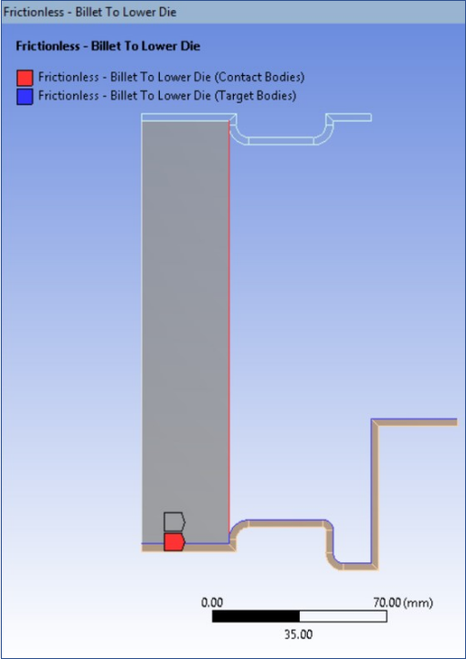
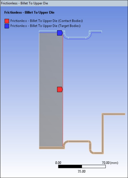
Frictionless contact is created between Billet and Dies to use Augmented Lagrange formulation with Update Stiffness at Each Iteration.
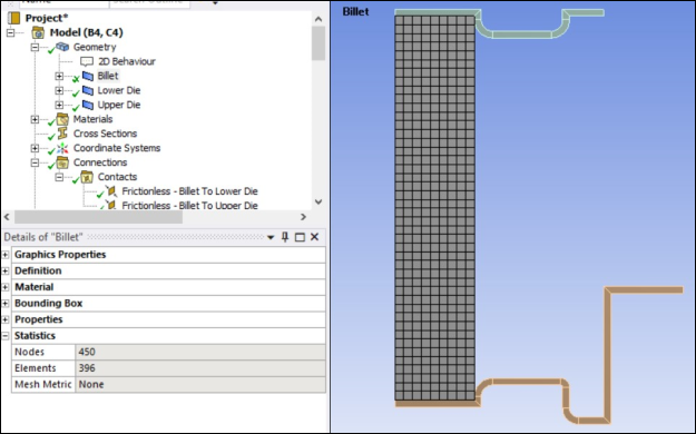
Mapped Face meshing is applied on the Billet Body to create lower order Quadrilateral elements using Edge Sizing to get 9 X 44 elements along length and height, respectively.
The B-bar method and the mixed u-P formulation prevent the volumetric locking that can be triggered by large plastic deformation.