Two local coordinate systems are created that are used to define remote displacements.
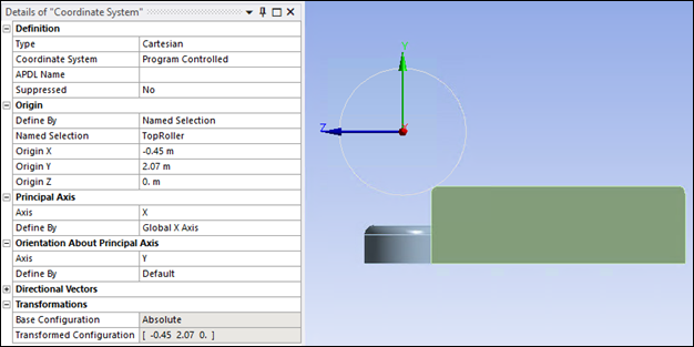
Create a coordinate system and scope it to the Named Selection"TopRoller" body with details shown in the figure below so that the X axis is aligned with the axis of the top roller.
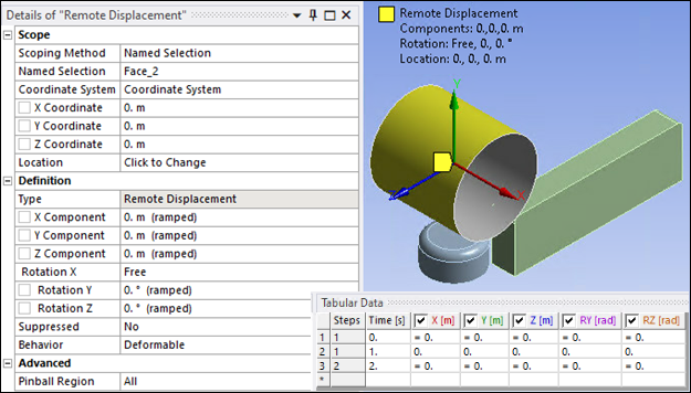
Create a Remote Displacement scoped to top roller face (Named Selection "Face_2") and the local coordinate system described above in Figure 27.15: First Coordinate System to set top roller rotation around its axis to Free and constrain it in all other directions.
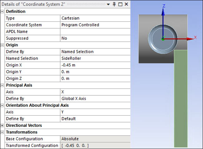
Create a second coordinate system and scope it to the Named Selection"SideRoller" body with details shown in the figure below so that the Y axis is aligned with the axis of the side roller.
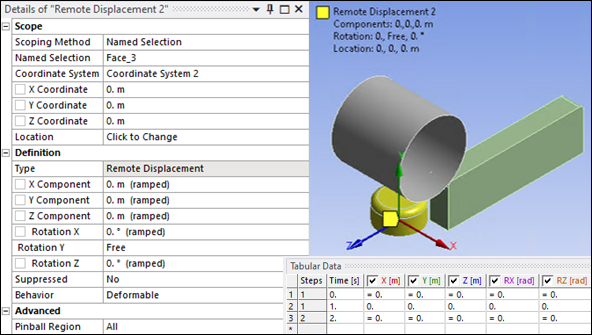
Create a second Remote Displacement scoped to side roller face (Named Selection"Face_3") and the local coordinate system described above in Figure 27.17: Second Coordinate System to set side roller rotation around its axis to Free and constrain it in all other directions.
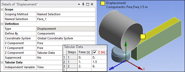
A Displacement along global Z direction is applied to the top face of the block (Named Selection"Face_1"). The block is displaced to 1.5 m in load step 1 and then to 6 m in load step 2 along global Z direction.
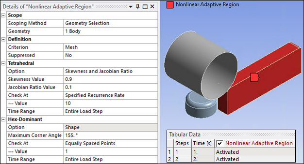
To enable adaptive mesh regeneration during the simulation, create a Nonlinear Adaptive Region and scope it to the block body with the following settings:
Set Criterion to Mesh
Select Skewness and Jacobian Ratio Option.
Set Skewness Value to 0.9 and Jacobian Ratio Value to 0.1.
Set Recurrence Rate to 10 for Time Range of entire load step.