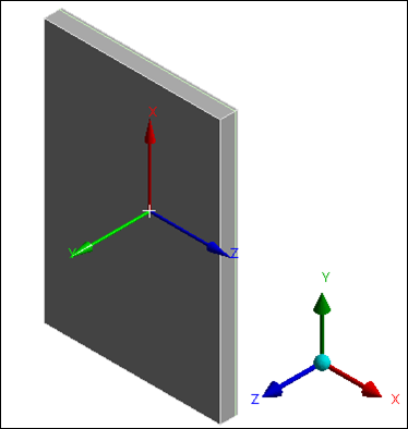
The element formulation for the concrete is based on SOLID185 linear brick elements. The solid geometry is meshed with 30 elements in each horizontal direction and 4 elements over the depth of the concrete slab.
The steel armoring is modeled using a smeared continuum approach and shares the same nodes as the surrounding concrete. Set up the reinforcement specifications as follows:
Select the Reinforcement option for the Model Type property for the concrete slab surface body.
Create a local coordinate system at the same location as the global coordinate system and rotate it so that the Y axis is normal to the concrete slab and the X axis is along its length to define the orientation of the reinforcement fibers as shown below.
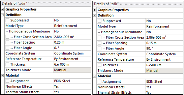
Define two reinforcements on surface bodies named xdir and zdir scoped to the newly created coordinate system as detailed below.
To create Idealized supports, the first layer of solid elements is modeled with linear concrete material properties, and the rest of the solid elements comprise the nonlinear layer. To achieve this, create two Named Selections using the Worksheet Criteria:
After meshing is complete, create the linear element layer named selection with the following criteria and rename it "LinearLayer".

For the rest of the solid elements, create a second named selection with the following criteria and rename it "Non-LinearLayer".

These two named selections are used to assign material properties as detailed in Material Properties.
To specify the elastoplastic tangent information for the concrete material properties, insert a Commands (APDL) object and add the following commands snippet.

/PREP7
et,1000,185,,3
esel,s,ename,,185
emodif,all,type,1000
ALLSEL
TB,CONCR,1,,,MSOL
TBDATA,1,2,1,1e-3,100,10,1e-20
ALLSEL


