The dimensions of the concrete slab considered here are 6 m x 4 m x 0.2 m. The structure is affected by both its dead load and a surface-pressure load. The surface-pressure load is increased until failure occurs.
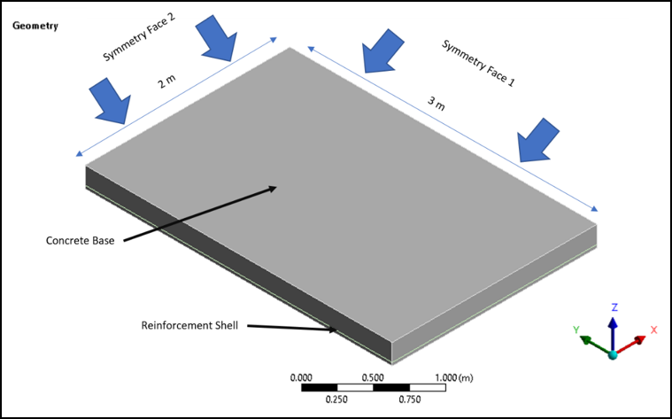
The border of the structure is supported in the vertical y direction. Due to symmetry conditions, it is possible to simplify the model. The finite element model includes the symmetry boundary conditions on the cutting planes of the resulting quarter model as shown in Figure 49.1: Quarter Symmetric Geometry for Load Limit Analysis.
The slab is composed of concrete as the base matrix material incorporating a steel grid reinforcing structure to absorb stresses that might develop under bending movement.
The reinforcing grid lies at a depth of hr = 0.17 m. The armoring has an equivalent distribution area of Asx = 3.39 cm2/m in the x direction, and Asz = 1.57 cm2/m in the orthogonal z direction. The distance between successive reinforcing elements is Δdx = 0.8 m for elements acting in the global x direction and Δdz = 0.6 m for elements acting in the global z direction. The reinforcing grid is simulated as a surface labeled "Reinforcement Shell" in Figure 49.1: Quarter Symmetric Geometry for Load Limit Analysis. Specifically, two surface bodies, and , were imported as geometry objects at 0.03 m from the bottom of the Concrete Base. They are used to model the reinforcement elements acting in the X and Z direction as described in Modeling and Meshing.
To account for the boundary singularities resulting from the idealized vertical support conditions, the first element layer that connects to the support is defined as linearly elastic. This can also be modeled as a separate body. In this analysis, that element layer is redefined using a command snippet.