


The analysis settings and solution controls differ depending upon the method used to solve a brake-squeal problem. This section describes two possible methods:
A linear non-prestressed modal analysis is effective when the stress-stiffening effects are not critical. This method requires less run time than the other method since Newton-Raphson iterations are not required. The contact-stiffness matrix is based on the initial contact status.
Following is the process for solving a brake-squeal problem using this method:
From the Toolbox, drag a Modal analysis system to the Project Schematic in workbench. Import the Brake assembly geometry, and set up the model as shown before.
Set the Solver Type to Unsymmetric in the Analysis Settings of Modal analysis. Perform a complex modal analysis using the QRDAMP or UNSYM eigensolver.
When using the QRDAMP solver, you can reuse the symmetric eigensolution from the previous load steps (QRDOPT), effective when performing a friction- sensitive/parametric analysis, as it saves time by not recalculating the real symmetric modes after the first solve operation.
Insert the following command snippet under Modal Analysis to generate sliding frictional force (CMROTATE).
/SOLU                     ! ENTER SOLUTION
ESEL,S,ENAME,,170         ! Chose Target elements on Disc 1
ESEL,R,CENT,Z,0
CM,SEL_A,ELEM             ! Make a component of Target elements
ALLSEL
ESEL,S,ENAME,,170         ! Chose Target elements on Disc 2
ESEL,R,CENT,Z,0.035
CM,SEL_B,ELEM             ! Make a component of Target elements
ALLSEL
CMSEL,S,SEL_A
CMSEL,A,SEL_B             ! Make a component to apply cmrotate
CM,EROT,ELEM
ALLSEL
CMROTATE,EROT,,,2
ALLSEL
For this analysis, the UNSYM solver is selected to solve the problem. (Guidelines for selecting the eigensolver for brake-squeal problems appear in Recommendations.)
Ensure that the Small Sliding effects are switched to the ‘OFF’ state under the Frictional contact behavior. This is true only for this method.
The frequencies obtained from the modal solution have real and imaginary parts due the presence of an unsymmetric stiffness matrix. The imaginary frequency reflects the damped frequency, and the real frequency indicates whether the mode is stable or not. A real eigenfrequency with a positive value indicates an unstable mode.
A full nonlinear perturbed modal analysis is the most accurate method for modeling the brake-squeal problem. This method uses Newton-Raphson iterations for static solutions.
Following is the process for solving a brake-squeal problem using this method:
From the Toolbox, drag a Static Structural analysis system to the Project Schematic in workbench. Import the Brake assembly geometry, and set up the model as shown before.
In the Analysis Settings, set the number of steps to 2.
Perform a nonlinear, large-deflection static analysis (NLGEOM,ON) by setting the Large Deflection option to On in the analysis settings under Static Structural System.
Use the unsymmetric Newton-Raphson method (NROPT,UNSYM) by setting the Newton-Raphson option to Unsymmetric in the Nonlinear Controls.
Restart Controls : specify the Restart Points needed for the linear perturbation analysis (RESCONTROL) by setting the Generate Restart Points option to Manual and then setting the writing of substep files to a Specified Recurrence Rate of 1.
Generate sliding contact (CMROTATE) to form an unsymmetric stiffness matrix. Insert the following code into a command snippet. This command snippet is to be executed in the first step to create the component EROT to be used in the second step.
/SOLU                     ! ENTER SOLUTION
ESEL,S,ENAME,,170         ! Chose contact elements on Disc 1
ESEL,R,CENT,Z,0
CM,SEL_A,ELEM             ! Make a component of contact elements
ALLSEL
ESEL,S,ENAME,,170         ! Chose contact elements on Disc 2
ESEL,R,CENT,Z,0.035
CM,SEL_B,ELEM             ! Make a component of contact elements
ALLSEL
CMSEL,S,SEL_A
CMSEL,A,SEL_B             ! Make a component to apply cmrotate
CM,EROT,ELEM
ALLSEL
Insert another command snippet and set the execution step to the second step. Insert the following commands into the second command snippet.
/SOLU                     ! ENTER SOLUTION
CMROTATE,EROT,,,20
ALLSEL
After obtaining the second static solution, postprocess the contact results.
Evaluate the contact status to determine whether the elements are sliding and the sliding distance, if any. This can be done by inserting a Contact Tool and a Status and Sliding Distance result object within the contact tool.
To conduct a pre-stressed Modal analysis, insert a Modal analysis system in the Project Schematic.
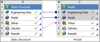
See that the pre-stressed environment is automatically set to the Static Structural System that it is. Also verify whether the Contact Status is set to Use True Status.
In the Analysis Settings, set the Solver type to Unsymmetric and the number of modes to expand to 30.