


VM-WB-MECH-111
VM-WB-MECH-111
Microstrip Transmission Line Capacitance
Overview
|
Reference: |
Beren, J. & Kaires, R. (1983). EMGAP solves electromagnetic problems using finite element analysis. Tektronix Internal Publication, Beaverton, OR. |
|
Solver: |
Ansys Mechanical |
|
Analysis Type(s): |
Coupled Field Static |
|
Element Type(s): |
2D Plane Stress |
Test Case
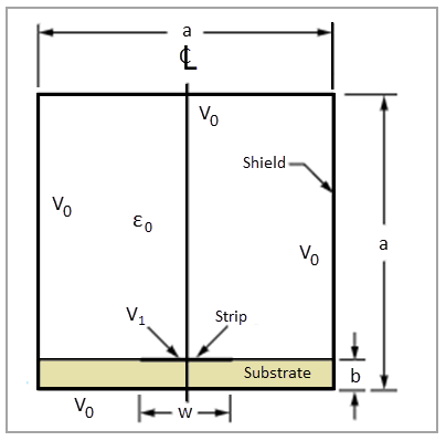
A shielded microstrip transmission line consists of a substrate, a microstrip, and a shield. The strip is at a potential V1, and the shield is at a potential V0. Determine the capacitance of the transmission line.
This problem is also presented in VM120
in the Mechanical APDL Verification Manual.
Materials Properties Tables
| Material Properties | Geometric Properties | |||||
|---|---|---|---|---|---|---|
|
Substrate:
Shield:
|
|
Analysis Assumptions and Modeling Notes
The capacitance of the device can be calculated from electrostatic energy and the applied potential difference as
| We = 1/2 × C × (V1-V0)2 |
where We is the electrostatic energy and C is the capacitance. The electrostatic energy is available by summing the energies of all the elements in the model in /POST1. Additional postprocessing includes displaying equipotential lines and the electric field as vectors.
To invoke the CMATRIX macro, the exterior nodes of each conductor must be grouped into individual components using a Named Selection. Each set of independent components is assigned a component name with a common prefix followed by the conductor number as shown in image below (A). A conductor system with a ground must also include the ground nodes as a component. The ground component is numbered last in the component name sequence.
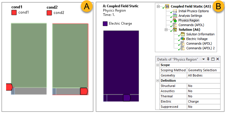
The Electric definition must be set to Charge for an active, pure electrostatic effect (B, above). Below are the commands for computing the capacitance. Additional information on CMATRIX can be found in the Ansys Mechanical APDL Command Reference.
Commands to compute capacitance using CMATRIX:
n_conductors=2 ! NUMBER OF CONDUCTORS IN SYSTEM
/assign,rst,file,rth ! MAPDL WILL CREATE file.rst. MECHANICAL EXPECTS file.rth

/solu
outres,all,all
cmatrix,2,'cond',n_conductors,0, ! EXECUTE CMATRIX MACRO
pars,all,cmatrix,parm ! SAVE CMATRIX RESULTS TO PARAMETER FILE
Commands to print capacitance:
parr,,cmatrix,parm
my_cmatrix_lll = abs(cmatrix(1,1,1))*1E12 !pF/m
my_cmatrix_112 = abs(cmatrix(1,1,2))*1E12 !pF/m
The finite element model uses a single 8-node 2D quadrilateral element (PLANE121).