VM-WB-MECH-016
VM-WB-MECH-016
Fatigue Tool with Non-Proportional Loading for Normal
Stress
Overview
| Reference: | Any basic Machine Design book |
| Solver(s): | Ansys Mechanical |
| Analysis Type(s): | Fatigue Analysis |
| Element Type(s): | Solid |
Test Case
A bar of rectangular cross section has the following loading scenarios.
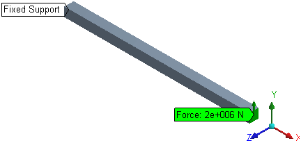
Scenario 1: One of the end faces is fixed and a force is applied on the opposite face as shown below in Figure 16: Scenario 1.
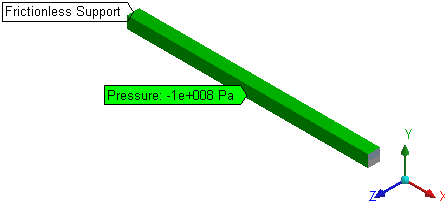
Scenario 2: Frictionless support is applied to all the faces of the three standard planes (faces not seen in Figure 17: Scenario 2) and a pressure load is applied on the opposite faces in positive y- and z-directions.
Find the life, damage, and safety factor for the normal stresses in the x, y, and z directions for non-proportional fatigue using the Soderberg theory. Use a design life of 1e6 cycles, a fatigue strength factor or 1, a scale factor of 1, and 1 for coefficients of both the environments under Solution Combination.
| Material Properties | |
|---|---|
| E = 2e11 Pa | |
| ν = 0.3 | |
| Ultimate Tensile Strength = 4.6e8 Pa | |
| Yield Tensile Strength = 3.5e8 Pa | |
| Endurance Strength = 2.2998e6 Pa | |
| Number of Cycles | Alternating Stress (Pa) |
| 1000 | 4.6e8 |
| 1e6 | 2.2998e6 |
|
|
Analysis
Non-proportional fatigue uses the corresponding results from the two scenarios as the maximum and minimum stresses for fatigue calculations. The fatigue calculations use standard formulae for the Soderberg theory.
Results Comparison
| Results | Target | Mechanical | Error (%) | |
|---|---|---|---|---|
| Stress Component - Component X | Life | 3335.1049 | 3329.9 | -0.156 |
| Damage | 299.8406 | 300.31 | 0.157 | |
| Safety Factor | 0.019 | 0.019025 | 0.132 | |
| Stress Component - Component Y | Life | 14765.7874 | 14653 | -0.764 |
| Damage | 67.724 | 68.247 | 0.772 | |
| Safety Factor | 0.04569 | 0.045378 | -0.683 | |
| Stress Component - Component Z | Life | 14765.7874 | 14766 | 0.001 |
| Damage | 67.724 | 67.725 | 0.001 | |
| Safety Factor | 0.04569 | 0.045696 | 0.013 | |


