


The application supports non-cyclic loading for Full Harmonic cyclic solutions. A load is non-cyclic when it varies between sectors and involves at least one harmonic index greater than zero.
The application considers the arbitrary forces acting on the full system as the sum of a finite number of spatial Fourier harmonics. The application analyzes the structure for each spatial harmonic index by applying constraint equations between the basic sector and duplicate sector. For each spatial Fourier harmonic, the program solves a corresponding equation, then expands and sums the calculated harmonics of the response to give the response for each substructure. Be sure to review the Limitations at the end of the section.
Tip: Review the Understanding the Solution Architecture section in the Mechanical APDL Cyclic Symmetry Analysis Guide for more information.
In Mechanical, you could specify the non-cyclic loading for the supported loads by setting the Non-Cyclic Loading Type property to or . You can then specify a desired Harmonic Index or Sector Number value. If you want to apply the load varying across several harmonic indices or sectors, you could specify the load Magnitude using Tabular Data, which varies based on the variable you specify.
Engine-order loading (traveling wave excitation) is a form of non-cyclic loading supported in Mechanical when you set the Non-Cyclic Loading Type property to . This section uses the terms harmonic index and engine order interchangeably.
Typically, engine-order loading is simply a count of the number of stators, combustion nozzles, etc., that cause the disturbance. An engine-order excitation typically occurs due to circumferential disturbances in the flow field, for instance from upstream stators or vanes.
The following examples illustrates how to apply loading based on specified inputs for the supported load types.
- Case 1: Constant Load and Constant Harmonic Index
The Pressure load illustrated here has constant loading and a constant Harmonic Index.
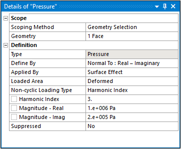
When you specify a Harmonic Index (HI), real and imaginary values of pressure (Preal and PImag), the contribution of the load at a sector
 is calculated as follows:
(15–1)
Where:

The values of the Harmonic Index specified should be:
1 to NS/2; if NS is even. 1 to (NS-1)/2; if NS is odd. - Case 2: Tabular Load with Harmonic Index as Independent Variable
You could also specify the loading applied to multiple harmonic indices using tabular data as illustrated here:
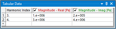
The load is expanded using Fourier transform as specified in Equation 88 above, for each harmonic index and their contributions are applied for each sector.
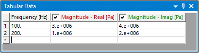
- Case 3: Tabular Load with Frequency (or X, Y, Z) as Independent Variable
The load specified at each frequency is expanded using Fourier transform as specified in Equation 88 above, and their contributions are applied for each sector.
Review the following limitations for the Non-Cyclic Loading Type feature:
- General
When you have a non-cyclic Tabular Load and the Independent Variable property is set to Frequency, please ensure that you define the load such that there is a non-zero magnitude for the load at each frequency point in the tabular data. Otherwise, the application may ignore some of these defined loads.
A Remote Point scoped to a Sector is equivalent to having one Remote Point for each Sector in the expanded solution.
If you specify a node-based load, such as Direct FE loads, Remote Force, Moments, etc., on both the low and high edge nodes, it will be taken into account twice in the solution due to the cyclic constraint equations.
- Engine-Order Loading
Applying a Remote Force, Moment, or Nodal Force in the direction that does not align with the Z direction of the cyclic axis could generate harmonic indices other than the ones requested.
Defining a non-cyclic loads using the option is not currently supported.
See the Modeling and Loading Limitations section in the Mechanical APDL Cyclic Symmetry Analysis Guide for more information.