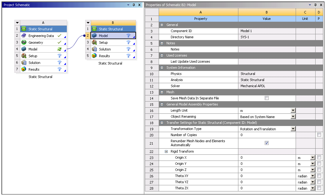
Similar to defining Mesh-to-Mesh Connections, Model-to-Model linking provides certain Project Schematic properties on the downstream Model cell prior to import. These properties can be grouped into two categories as described below.

General Model Assembly Properties
The following properties are applicable to all the objects imported into the downstream system.
|
Property |
Description |
|---|---|
| Length Unit |
Units in which the geometry is assembled in Mechanical. |
| Object Renaming | Downstream system allows you to rename imported objects to easily identify the source of the object and also to differentiate objects from different sources with same name. The drop-down list of automatic naming options includes:
|
| Group Objects By Source | Select the checkbox to automatically group the various source objects created/imported during the assembly process. The assembly process can generate a large number of objects. Grouping them enables you to more easily manipulate the objects in the tree structure. This feature works independently or it can group existing groups of objects that you have defined in an upstream system(s). See the Grouping Tree Objects section of the Help for additional information. Note:
|
Transfer Settings for "System Name"
Similar to importing mesh-based files using the External Model component system, these properties are applicable to each source (upstream) model imported into the downstream system.
Note: The application does not apply Rigid Transform values if they expand to the "identity transformation." The identity transformation is when the values for Origin X, Origin Y, Origin Z are all zero (within a tolerance) and Theta XY, Theta YZ, Theta ZX are all multiples of 360 degrees (within a tolerance). The application uses an absolute and relative tolerance equal to the 2D Tolerance specified in the Geometry category of the Options preferences. You can change the specified default value (1e-5) using the preference dialog.
|
Property |
Description | ||
|---|---|---|---|
| Transformation Type | You use this property to apply a transformation to your upstream model. The transformation options for this property include (default) and .
Note: For the Rotation and Translation option, transformations are applied in the following order:
| ||
| User Specified Tag |
This property allows you to append a label on to the name of the imported objects. The default value is the System Name from the upstream model. This property is only visible when the Object Renaming property is set to . | ||
| Number of Copies |
Specifying a number of copies greater than zero creates copies of the source mesh. For example, if you import a Mechanical Model with a single part and set Number Of Copies to 2, you will get three parts in the downstream Mechanical system. | ||
| Renumber Mesh Nodes and Elements Automatically | This property is active by default and automatically renumbers the nodes and elements of your assembly. Deselecting this option maintains the existing node and element numbering. Any numbering duplication and the application will display an error condition. You can modify node and element numbers with the Mesh Numbering feature once you import your assembly into Mechanical. | ||
| Rigid Transform ( = ) | Transform the Original: This property is only available when Number Of Copies is set to 1 or greater. Select the checkbox if you want to apply the specified transformation to the source mesh. Origin X, Y, and Z: Translate the origin of the model along the X, Y, or Z axis. If you specify any copies, the translation will be applied relative to the previous copy (or source mesh in the case of the first copy). Theta XY, Theta YZ, and Theta ZX: Rotate the model about its origin in the XY, YZ, or ZX plane. If you specify any copies, the rotation will be applied relative to the previous copy (or source mesh in the case of the first copy). | ||
| Mirror Transform ( = ) | Plane Point X/Y/Z These properties enable you to define the coordinates of a point on the mirroring plane. Plane Normal X/Y/Z: These properties enable you to define a vector that is normal (orthogonal) to the mirroring plane. |


