


Introduction
Source models may need to be transformed (translated and rotated in space) to position and align them. The transformations can be pre-calculated or you may need to calculate the transformations based on the fit of your different sub-models. For example, you may need to align the hole from one model to the bolt from another model.
There are two methods available to specify the rigid transformations for a source model:
Specifying Rigid Transform properties in Transfer Settings for each Source Model. These settings are useful if the required translation and rotation values are already available, or can easily be calculated for a source.
Using the Worksheet on the Model node in the assembled system that enables you to properly position and align your source models using coordinate systems that you import from sources systems or that you create in Mechanical for the assembled system. The details of alignment using Worksheet are discussed below.
Specifying Rigid Transforms Using the Worksheet
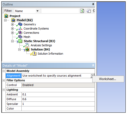
You access the Model Assembly Worksheet by selecting the Model object in Mechanical and the selecting the fly-out menu of the Alignment property, as shown below, or by selecting the Worksheet button on the Home Tab.
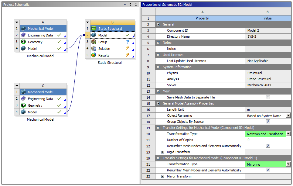
The Transfer Settings selections you make on the Workbench Project page determine what is displayed in the Mechanical Worksheet. In the example below, Rotation and Translation and Mirror Transform have both been specified. The Worksheet sections populate based on your Transformation Type entries.
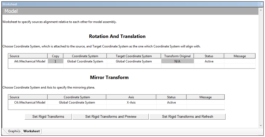
The Worksheet contains a row for every Mechanical source model. For Rotation And Translation, you need to specify a source and a target coordinate system, for each source model. For alignment, the transforms are calculated such that the source coordinate system after transformation is aligned with the target coordinate system. For Mirror Transform, you need to specify a Coordinate System and an Axis to define the mirroring plane.
Example
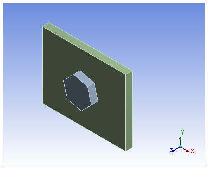
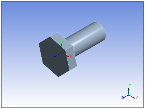
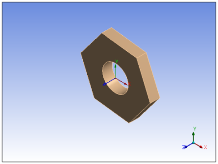
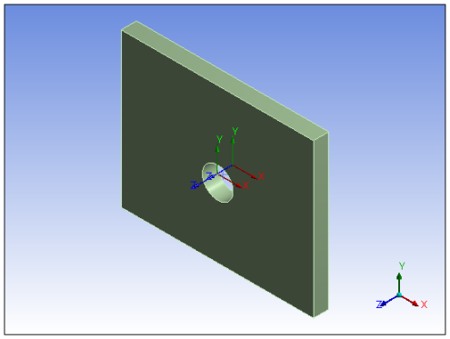
The following example demonstrates the assembly of three components (a bolt, plate, and nut) using the Rotation and Translation transformation. The unassembled geometry is shown below.
|
|
|
In this example, the plate needs to be aligned between the bolt head and the nut. To specify alignment, the following coordinate systems are created:
Coordinate System (Bolt): Centered at intersection of bolt axis and base of the bolt head.
Coordinate System (Nut): Centered at intersection of nut axis and top face of the nut.
Coordinate System (Plate - Bolt) and Coordinate System (Plate - Nut): Centered at intersection of hole axis and top and bottom faces of the plate, respectively.
You use the features of the Worksheet to specify alignment. In the following example, the:
bolt is in its desired location so no transforms are specified for the bolt.
plate needs to be aligned with the bolt head. The Coordinate System (Plate - Bolt) is specified as source coordinate system and Coordinate System (Bolt) is specified as target coordinate system.
top face of the nut needs to be aligned with bottom face of the plate so Coordinate System (Nut) is specified as source coordinate system and Coordinate System (Plate-Nut) is specified as target coordinate system.
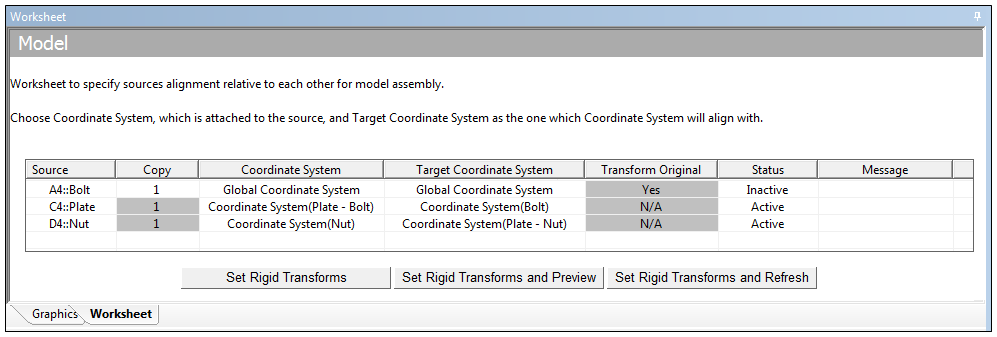
Once the transforms are specified using coordinate systems, you have three options to update the rigid transform values in workbench, which include:
Set Rigid Transforms: Calculates rigid transform value and sets them in Transfer Settings in Workbench
Set Rigid Transforms and Preview: Calculates rigid transform value, set them in Transfer Settings in Workbench and Preview Geometry.
Set Rigid Transforms and Refresh: Calculates rigid transform value, set them in Transfer Settings in Workbench and Refresh Model.
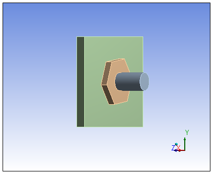
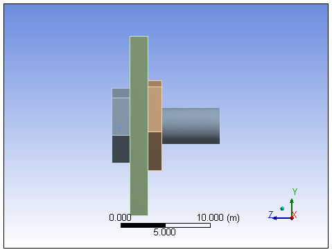
The assembled system is shown below.
The worksheet contains the following additional columns:
Copy: Enables you to specify a copy of the model that needs to be aligned. Calculates the transforms such that the specified copy is aligned with the target coordinate system.
Transform Original: Enables you to control Transform Original property when the number of copies is greater than zero. If the specified is , then the field is read-only and set to .
Status: Enables you to control how the transformations specified (using Coordinate System and Target Coordinate System) in a particular row are applied during Rigid Transform calculation. Options include:
: The application performs a complete calculation to align Coordinate System with Target Coordinate System.
: The transformations for the Source are not calculated. The model does not move as a result of calculating Rigid Transforms.
: The application locks the source relative to the target, i.e. the source moves by the same amount the target does. This option is useful when, for example, you need to move a complete (and aligned) subassembly due to some additional requirement. In this case, for all sources of the subassembly, set the Status to and then specify the transformation (using Coordinate System and Target Coordinate System) only for the root node (first source in the chain).
: Displays any validation messages if any of the entry is invalid.
Note: For legacy databases (created in Mechanical version 15.1 or before), the Worksheet for alignment is only available once you have reassembled your model in the current version.