


The Mesh system launches multiple meshing and geometry applications, allowing you to create and/or open geometry or mesh files.
To work through a Mesh, add it to the Project Schematic using any of these methods:
Double-click the Mesh component system template in the Toolbox.
Drag-and-drop the Mesh component system template onto the Project Schematic.
Drag-and-drop a .meshdat or .cmdb file from Windows Explorer onto the Project Schematic.
From the menu bar, select > or click the button and select a .meshdat or .cmdb file.
For standard context menu options, see System Header Context Menu Options and Geometry. The following table describes the context menu actions specific to the Mesh system.
| Menu Item | Description |
|---|---|
| System Header | |
| Replace With > Mechanical Model | Replaces the Mesh component system with a Mechanical Model component system. |
| Mesh Cell | |
| Edit | Opens the Meshing application and loads an existing geometry or mesh file. |
| Import Mesh File | Imports read-only meshes for downstream application use. For more information see Importing Read-only Meshes for Downstream Application Use |
| Duplicate | Duplicates the Mesh system. The Geometry cell is shared, and all data associated with the Mesh cell is copied to the second system. |
| Transfer Data To New | Transfers a mesh into one of the following downstream systems:
|
Multiple Mesh component systems can be merged together by creating a connection between the Mesh cells of each component system. This allows you to build up more complicated meshes from smaller, simpler meshes.
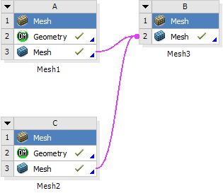
For every upstream Mesh cell connected to a downstream Mesh cell, a new set of properties called Transfer Settings for [Mesh component name] appears in the Properties pane of the downstream Mesh cell. In the above example, with two upstream Mesh components connected to single, downstream Mesh component, the Properties pane of the downstream Mesh (cell B3) has two new groups of properties.
Similarly, a Renumber Mesh Nodes and Elements Automatically
property appears for each transfer. This property in the downstream mesh cell
controls whether mesh nodes and elements are automatically renumbered to prevent
conflicts. You can set the Renumber Mesh Nodes and Elements
Automatically property on a transfer-by-transfer basis. By default,
automatic renumbering occurs but you can disable the property for as many of the
transfers as you want—as long as their element numbers do not conflict
downstream and the Number Of Copies is set to
0.
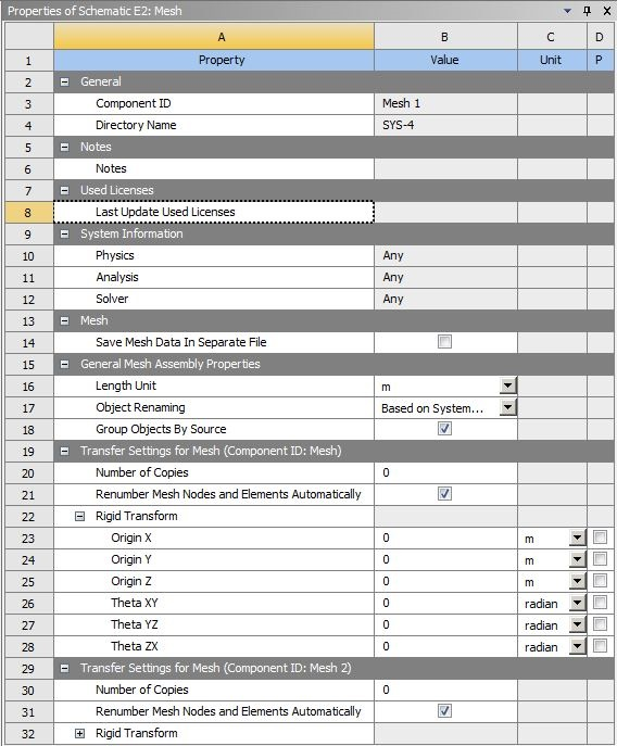
Table 5: Properties Pane: General Properties
| Property | Description |
|---|---|
| Length Unit | This property sets the units for the downstream mesh assembly. After the meshes are initially assembled, this property becomes read-only. You must reset the downstream mesh cell in order to change the Length Unit. |
Table 6: Properties Pane: Transfer Settings Section
| Property | Description |
|---|---|
|
Number Of Copies | When set to zero (default), only the source mesh is transformed.
If you specify a number of copies greater than zero, these will be
in addition to the source mesh. For example, if you import a .cdb
file with a single part and set Number Of
Copies to 2, you will get
three parts in Mechanical. |
| Renumber Mesh Nodes and Elements Automatically | When Mesh cells are connected, this property in the downstream
Mesh cell controls whether mesh nodes and elements are automatically
renumbered to prevent conflicts. If the Number Of
Copies is set to |
| Transform Original | This property is available only when Number Of
Copies is set to 1 or greater.
Select the check box if you want to apply the specified
transformation to the source mesh as well as any copies. |
| Origin X/Y/Z | These properties allow you to translate the origin of the model along the X, Y, or Z axis. If you specify any copies, the translation is applied relative to the previous copy (or source mesh in the case of the first copy). |
| Theta XY/YZ/ZX | These properties allow you to rotate the model about its origin in the XY, YZ, or ZX plane. If you specify any copies, the rotation is applied relative to the previous copy (or source mesh in the case of the first copy). |
Any change in these properties will put the downstream mesh in a Refresh Required state.
You can preview the mesh transformations by right-clicking on the Mesh cell and selecting Preview Assembled Geometry. Use this feature to confirm that the correct mesh transformations have been applied. For more details and an example workflow, see Preview Assembled Geometry.