This section illustrates the details of assembling geometry using an example of a three-part a pendulum joint model.
The Assemble feature enables you to bring in CAD geometry that may initially be in a state of disassembly. After importing the CAD geometry, you can actively assemble the different parts and Set them in the assembled configuration for the start of the analysis.
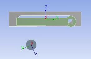
The geometry shown for the example in Figure 9.1: Initial Geometry was imported into a Rigid Dynamics analysis System.
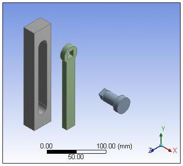
This geometry consists of three bodies. In Figure 9.1: Initial Geometry they are (from left to right) the Basis, the Arm, and the PendulumAxis. These three bodies have been imported completely disjointed/separate from each other.
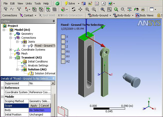
The first step to orient and assemble the bodies is to add a Body-Ground Fixed joint to the body named Basis. To do this:
Select the Connections object from the Outline.
From the Connections Context tab, open the drop-down menu and select .
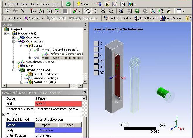
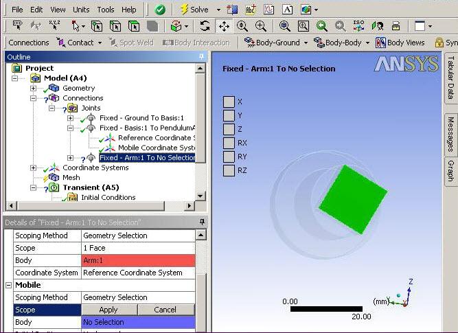
Select a flat external face on the Basis body as seen in Figure 9.2: Selecting a Face for a Body-Ground Fixed Connection.
In the Details view under Mobile, click in the Scope field and select .
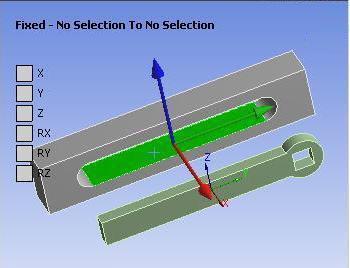
Next, you need to join the PendulumAxis to the Basis. Since they are initially disjoint, you need to set two coordinate systems, one for the Basis and the other for the PendulumAxis. Additionally, to fully define the relative position and orientations of the two bodies, you must define a fixed joint between them. To do this:
From the Connections Context tab, open the Body-Body drop-down menu and select .
Highlight the face on the Basis as shown below.
In the Details view, click the Scope field under Reference and select .
Select the cylindrical face on the PendulumAxis.
In the Details view, select the Scope field under Mobile and select Apply.
Also, change the Initial Position value under Mobile from to .
Now, the joint has two coordinate systems associated with it: A Reference and a Mobile coordinate system.
Next, you must associate the Reference and the Mobile Coordinate Systems to the respective bodies with the appropriate orientations. To associate the Reference Coordinate System to the respective bodies:
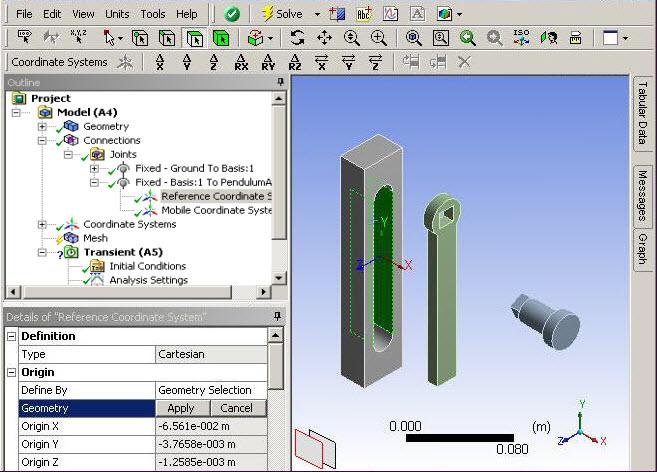
In the Outline, highlight Reference Coordinate System.
In the Details view, click the box next to Geometry under Origin.
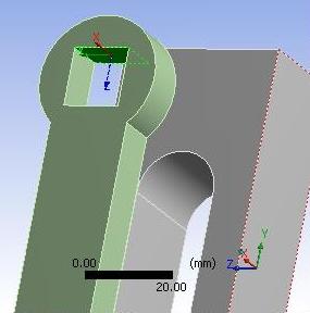
Select the two internal rectangular faces on the Basis as shown in Figure 9.4: Creating the Reference Coordinate System and in the Details view, select Apply. This will center The Reference Coordinate System at the center of the hole on the Basis.
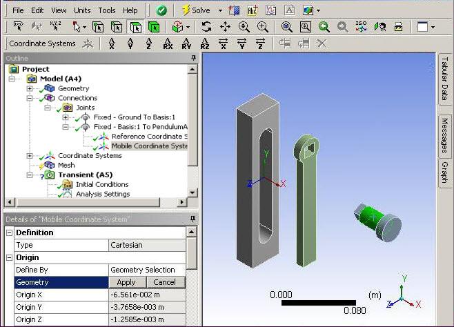
To associate the Mobile Coordinate System to the respective bodies:
Highlight the Mobile Coordinate System (this coordinate system is associated with the Basis).
In the Details view, click in the Geometry field under Origin.
Select the cylindrical surface on the PendulumArm.
In the Details view, click .
Next, you will need to orient the PendulumAxis coordinate system so that it is oriented correctly in the assembly:
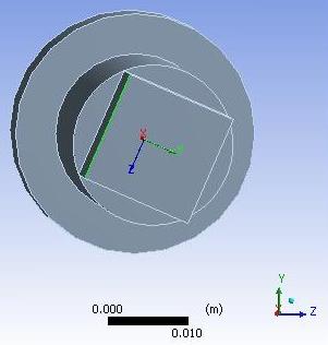
In the Mobile Coordinate System associated with the PendulumAxis, click in the box next to Geometry under Principal Axis (set to Z).
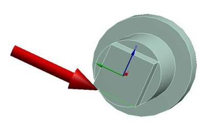
Select one of the vertical edges on the PendulumAxis such that the Z axis is parallel to it as shown in Figure 9.6: Orienting the Pendulum Axis. In the Details view, click .
With Mobile Coordinate System highlighted in the Outline, select the x-offset button on the Context tab.
In the Details view, enter an Offset X value of 2.5mm to align the faces of the PendulumAxis with the Basis.
Note: The transformations available allow you to manipulate the coordinate systems by entering offsets or rotations in each of the 3 axis.
The two coordinate systems that were just defined should look similar to the figure below.
Next, you will need to define the coordinate systems to join the Arm to the PendulumAxis during assembly.
From the Context tab , select Body-Body > .
To define the Reference Scope, choose one of the faces of the Arm that will be connected to the PendulumAxis then select .
Now, configure the Mobile Scope by selecting the flat end face of the PendulumAxis as shown in Figure 9.8: Scoping the Mobile Coordinate Systems, then select .
Set the Initial Position under Mobile from to .
Finally, set the Origin of the Reference Coordinate System to the center of the hole in the Arm using the same procedure described above for the Basis.
Next, you will need to offset the Coordinate System associated with the Arm so that the faces on the Arm are aligned with the end face of the PendulumAxis.
With Reference Coordinate System highlighted, select the x-offset button on the Context tab.
Enter an Offset X value of -5mm.
Note: The transformations available allow you to manipulate the coordinate systems by entering offsets or rotations in each of the 3 axis.
Next, highlight the Mobile Coordinate System. This coordinate system is associated with the Arm. Click the box next to Geometry under Origin
Select the flat surface on the PendulumArm and click .
Now you will need to orient the PendulumAxis so that its faces are aligned with the faces on the Arm during the Assemble process.
Highlight the Mobile Coordinate System that is assigned to the PendulumAxis.
From the Details view, click the in the Geometry field under Principal Axis and select an edge of the PendulumAxis as shown in the figure.
Under Principal Axis In the Details view, select Apply in the Geometry field to orient the PendulumAxis to this edge.
Now that the three bodies have been oriented and aligned, they are ready to be assembled.
In the Outline, highlight Connections.
From the Context tab, select .
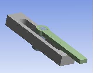
The parts should snap together in place and resemble Figure 9.10: Assembled Geometry. If the geometry you're attempting to assemble has not snapped into place as expected, you should retrace your previous steps to make sure that the coordinate systems are properly oriented. If your assembly has been successfully performed, then click Set on the Context tab to place the assembly in its assembled position to start the analysis.