


Orientation may be defined by any of the following geometric selections:
A planar face (normal to).
A straight edge.
Cylindrical or revolved face (axis of).
Two vertices.
This section discusses the following topics:
Direction Defaults
If you insert a load on selected geometry that includes both a magnitude and a direction, the Direction field in the Details view states a particular default direction. For example, a force applied to a planar face by default acts normal to the face. One of the two directions is chosen automatically. The load annotation displays the default direction.
Highlighting Geometry in Select Direction Mode
Unlike other picking filters (where one specific type of geometry highlights during selection) the Select Direction filter highlights any of the following during selection:
Planar faces
Straight edges
Cylindrical or revolved faces
Vertices
If one vertex is selected, you must hold down the Ctrl key to select the other. When you press the Ctrl key, only vertices highlight.
Selecting Direction by Face
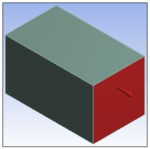
The following figure shows the graphic display after choosing a face to define a direction. The same display appears if you edit the Direction field later.
The selection blip indicates the hit point on the face.
Two arrows show the possible orientations. They appear in the lower left corner of the Geometry Window.

If either arrow is clicked, the direction flips.
When you finish editing the direction, the hit point (initially marked by the selection blip) becomes the default location for the annotation. If the object has a location as well as a direction (such as Remote Force), the location of the annotation will be the one that you specify, not the hit point.
Note: The scope is indicated by painting the geometry.