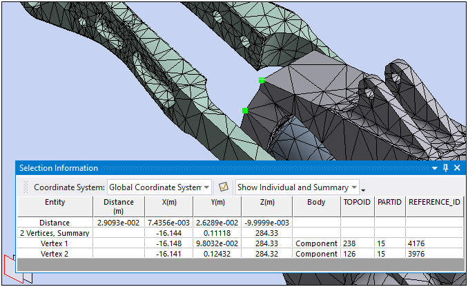
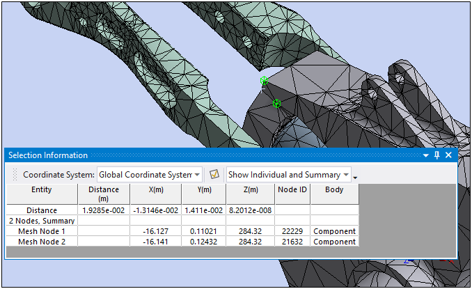
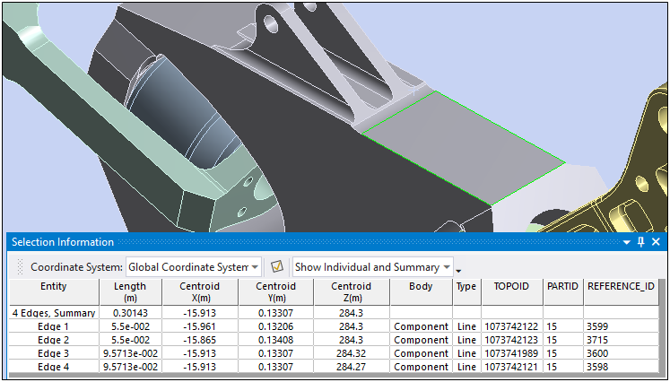
The supported selection modes are vertex, edge, face, body, node, and coordinate, as described below. Common reported information for each mode, except coordinate, includes x, y, z locations and if two selections are made, the distance between their centroids is reported.
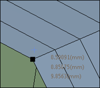
Vertex
Individual vertex location and average location are reported. The bodies that the vertex attaches to are also reported.
Node
The information displayed for selected nodes is similar to a vertex with the addition of the Node ID.
Edge
Combined and individual edge length and centroid are reported. The bodies that the edge attaches to are reported. The type of the edge is also reported. If an edge is of circle type, the radius of the edge is reported.
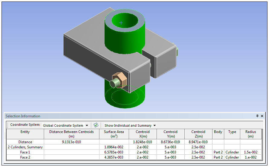
Face
Combined and individual area and centroid are reported. The bodies that the face attaches to are reported. The type of the face is reported. If a face is of cylinder type, the radius of the face is also reported.
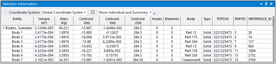
Body
Combined and individual volume, mass, and centroid are reported. The body name is reported. Your choice of the mass moment of inertia in the selected coordinate system or the principal is also reported. The choice is provided in the Selection Information Column Control dialog box.
Important: For a Surface Body, the Volume, Mass, and Moment of Inertia information for the Body selection are based on the original thickness value specified on the Surface Body object. This does not account for any Thickness object specifications. Thickness specifications overwrite the body thickness values when the application calculates thickness for any faces and/or surface bodies. Refer to the PRECISE MASS SUMMARY section from the Solution Information worksheet for solver calculated Mass values.
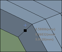
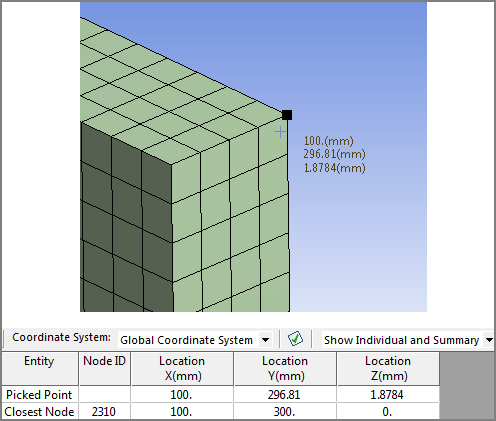
Coordinate
If there is a mesh present, the picked point location and the closest mesh node ID and location are reported.
In the case of a surface body model, the closest node will be located on the non-expanded mesh (that can be seen if you select the Thick Shells and Beams option from the Style group on the Display tab).
Non-expanded shell view:
Expanded shell view: