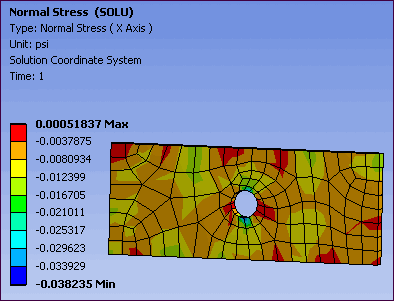
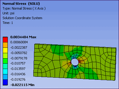
Solution Coordinate System is an option of the Coordinate System property in the Details view for most result objects. If you are familiar with the Mechanical APDL application commands, Solution Coordinate System is an implementation of the RSYS,SOLU command, where for element results, such as stress, a coordinate system is produced for each element. If these individual element coordinate systems are aligned randomly, you can re-align them to a local coordinate system to obtain a uniform alignment. Viewing results in the element solution coordinate system has value since results in a local coordinate system aligned with a certain shell direction are typically more meaningful than results in a global coordinate system. For example, seeing bending and in-plane stresses have meaning in a local coordinate system, but have no meaning in a global coordinate system. See the Additional POST1 Postprocessing section in the Mechanical APDL Basic Analysis Guide for additional information.
Important: For Beam and Pipe elements:
The following stress and strain component results are displayed in the element coordinate system:
Normal X, Y, and Z
Shear XY, YZ, and XZ
When a Line Body is specified as a beam/pipe that includes cross sections (SECDATA), beam strains/stresses always use the Solution Coordinate System, even if you specify the global coordinate system. To calculate beam strains/stresses, you need to set the Beam Section Results property of the Solution object to .
Application
The following are typical applications for viewing results in a solution coordinate system:
Viewing results in a particular direction for surface bodies or "solid shell" bodies, that is, solids meshed with the Solid Shell element option (see the Meshing Help: Sweep description in the Method Control section).
Viewing results in a random vibration, spectrum, or surface bodies in an explicit dynamics analysis. Results for these analysis types only have meaning in a solution coordinate system.
Background
The meshing of surface bodies and solid shell bodies result in coordinate systems whose alignment is on a per element basis, in contrast to solid body element types whose coordinate systems are aligned with the global coordinate system by default. Surface body alignment on a per element basis can lead to results with totally random alignment directions as shown below.

To produce meaningful results for surface body and solid shell bodies, you can re-align the random direction of each element's solution coordinate systems to a uniform direction of a local coordinate system. An example is shown below.

Procedure
To correct for random coordinate system alignments in surface bodies and solid shell bodies, and to ensure a consistent alignment:
For each part, create a local coordinate system to specify the alignment of the elements of the part.
Choose the Solution Coordinate System option for the result.
Note:
The Coordinate System setting for result objects in a random vibration or spectrum analysis is set to Solution Coordinate System by default and cannot be changed because the results only have meaning when viewed in the solution coordinate system.
In Explicit Dynamics analyses, the solution coordinate system only has meaning for results on surface bodies. For results with the Solution Coordinate System selected, all bodies scoped to the result with body types other than shell bodies will have the results displayed in the global coordinate system.
The solution coordinate system is only supported for beam elements in LS-DYNA analyses for results.


