


On the Windows platform, you can open Ansys EDB, ODB++, and IPC2851 ECAD files directly in Mechanical using the Geometry cell of the analysis system.
When you import ECAD files into Mechanical, the ECAD Import pane, illustrated below, displays automatically. Because printed circuit boards contain many detailed components, this feature enables you to either limit or expand the degree of detail for displaying a component and its bodies. Specifically, you can greatly simplify the display of complicated components that are not pertinent to your analysis and as a result speed up processes such as mesh and solution.
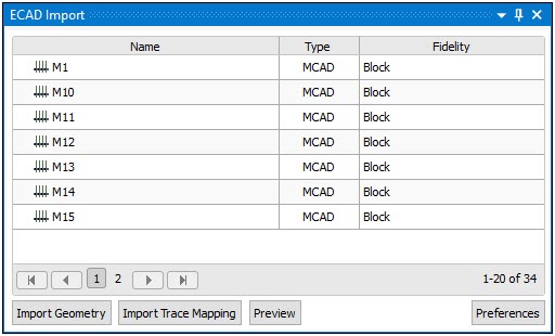
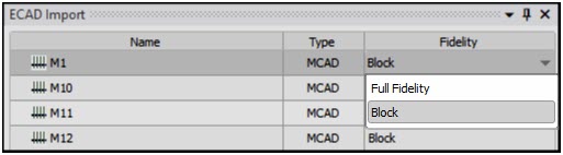
The first two columns of the pane list each part of your model by Name and Type. Parts can include PCBs, MCAD components (3D geometries representing board components like USB ports, power connectors), BGAs, etc. The Fidelity column enables you to specify whether to present a component as a (default) or to includes the detailed parts or bodies of the component using the option.
ECAD Import Pane Features
The ECAD Import pane provides the following options for your analysis:
- Import Geometry
This option imports your geometry into Mechanical. You can make fidelity changes before and after importing the geometry. You must select the Import Geometry button again in order changes to take effect.
- Import Trace Mapping
This option automatically links an upstream External Data system to the Model cell of your analysis on the Workbench project page and imports Trace Mapping data. An Imported Trace (Group) folder and its child object, Imported Trace, are automatically inserted under the Materials folder in the Outline.
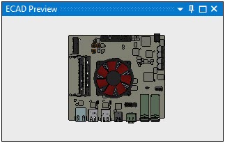
- Preview
The Preview option displays a rendering of your model. By default, before you import your geometry into Mechanical, the ECAD Preview pane renders it with all components in .
Once you select the button, the model renders in the Geometry window based on the settings of the ECAD Import pane. An example is illustrated here with all components using fidelity.
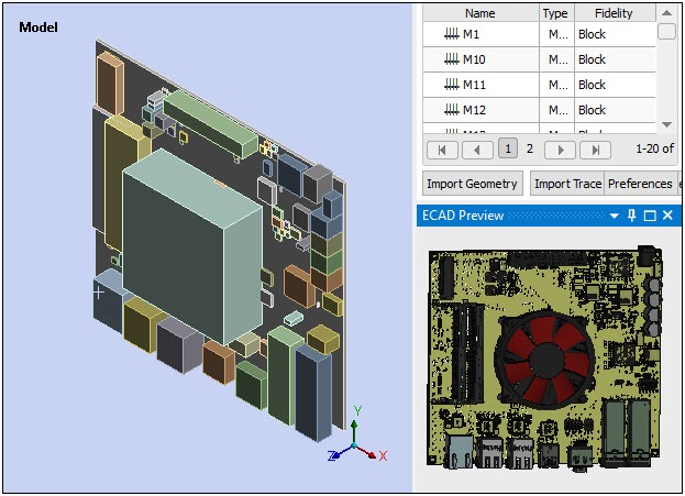
You can change the fidelity settings as desired and update the model rendering in the Geometry window using the Import Geometry button. Note that this action can invalidate scoping.
- Preferences
The Preferences button displays the dialog shown below. The options of the dialog are active by default. These options automatically take general import actions.
Dialog Preference Description 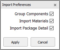
Automatically group bodies by component in the Preview window as well as in a folder under the Geometry object. Automatically import the materials contained in the ECAD file into Engineering Data. Only the materials from EDB files will be fully defined. For the other file types, you will need to complete their material property definition. Automatically import Intermediate Data Format (IDF) bodies present on your model.
Defining Fidelity following Import
In addition to the drop-down menu of each row in the ECAD Import pane, you can change the Fidelity using any of the following methods. Once a fidelity change is made to a component, you must select the Import Geometry button in order for it to take effect. Also note that re-importing the model can affect the scoping of associated components.
Select multiple rows simultaneously using the [Shift] key.
Select multiple rows individually using the [Ctrl] key.
Right-click one or more parts on the model in the Geometry window and select > or . This action also automatically displays the ECAD Import pane if it is not already displayed.