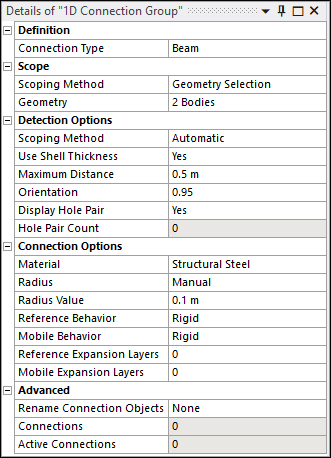
| Definition |
Connection Type: Options include
Beam, Contact,
Spring, and Joint.
|
| Scope |
Scoping Method: Options include Geometry
Selection (default) and Named Selection.
Geometry: Visible when Scoping
Method is set to Geometry Selection. Displays
the type of geometry and the number of geometric entities to which the
boundary has been applied using the selection tools. Named Selection: Visible when Scoping
Method is set to Named Selection. Provides a
drop-down list of available user-defined Named Selections.
|
| Detection Options |
To create connection objects, you need a reference/mobile or contact/target
pair. The following properties facilitate their detection, and the pairs are then
scoped to the connection objects as reference/mobile (for Beam, Spring and Joint)
or contact/target (for Contacts) entities.
Scoping Method: Options include
Automatic (default) and Manual. Automatic: Automatically defines entities as
reference and mobile or contact and target. Manual: Allows you to define geometric entities
(bodies, faces, or edges) separately to be considered as reference and
mobile or contact and target.
Use Shell Thickness: Options include
Yes (default) and No. When set to
Yes, the program takes into account the surface thickness
while detecting hole pairs. When set to No, the surface
thickness is not taken into account. Maximum Distance: Defines the maximum distance
between entities (hole edges) to be considered while detecting hole
pairs. Orientation: Specifies the misalignment allowance for
the algorithm to detect misaligned holes. The orientation value is equal to
the dot product of the vector joining the hole centroids and the surface
normal vector of the face connected to reference edges. This value is between
0 and 1, where 1 represents perfect alignment or coaxial holes. The lower the
value, the greater the misalignment allowed between holes. Display Hole Pair: Options include
Yes (default) and No. When set to
Yes, the program highlights detected hole pairs in the
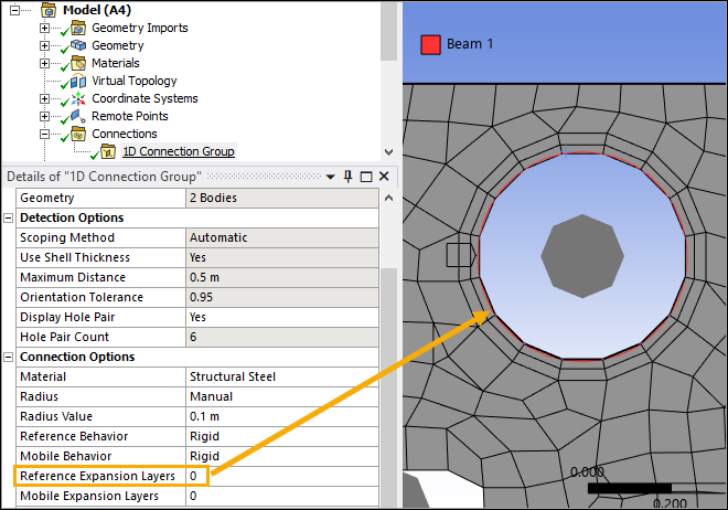
Geometry window. Hole Pair Count: Read-only property to display the
number of detected hole pairs.
|
| Connection Options |
The following properties act as global properties to generate all connection
objects at detected hole pair locations. Changing any property value updates all
generated connections automatically without the need to refresh or
regenerate.
Note: Each connection type allows certain properties to be changed. These
properties are visible in the Details pane of the 1D
Connection Group, while the remaining properties are hidden and kept as
default. Connection Options (Connection Type - Beam) Material: Provides a drop-down list of materials
for the beam from the predefined material list. Radius: Options include
Manual (default) and Automatic. Manual: Enables the Radius
Value property and allows you to enter the radius
value. Automatic: The program calculates the radius
from the scoped entity (the hole's radius). When the radii of the
reference and mobile holes are different, the smaller value between
them is used.
Reference Behavior: Specifies the scoped
reference geometry as either Rigid (default) or
Deformable. Mobile Behavior: Specifies the scoped mobile
geometry as either Rigid (default) or
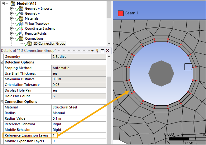
Deformable. For more information, see Geometry Behaviors. Reference Expansion Layers: Specifies the number
of layers of nodes around the reference hole to be scoped. By default, the
value is 0, meaning that the geometric edges
forming the hole are scoped. Any integer value greater than 0 will expand
the selection to the nodes that are attached to the specified number of
element layers around the hole. Mobile Expansion Layers: Specifies the number of
layers of nodes around the mobile hole to be scoped. The logic is the same
as described above for the Reference Expansion Layers
property. For more details about beam connections, see Beam Connections.
Connection Options (Connection Type - Contact) Contact Type: Only Bonded
contact type is currently supported. Formulation: Only MPC
formulation is currently supported. Contact Expansion Layers: Specifies the number of
layers of elements around the contact hole to be scoped. By default, the
value is 0, meaning that the geometric edges
forming the hole are scoped. Any integer value greater than 0 will expand
the selection to the specified number of element layers around the
hole. Target Expansion Layers: Specifies the number of
layers of elements around the target hole to be scoped. The logic is the
same as described above for the Contact Expansion
Layers property.
Note: If Target Expansion Layers is set to
0, element scoping is not permitted for contact
holes, and Contact Expansion Layers cannot be
greater than 0. However, the opposite is allowed. For more details, see
Scope Settings in Contact.
Pinball Region: Options include Program
Controlled (default) and Radius. Program Controlled: The application
automatically calculates the Pinball Region value. Radius: Enables the Radius
Factor property and allows you to enter the Radius Factor
value manually. The Pinball Radius for each contact is the product of
the Radius Factor and the distance between the corresponding contact
and target scoping. Selecting the Radius option for the Pinball
Region ensures that the contact is closed (provided that the
Radius Factor is greater than 1). With a 1D Connection Group, the scoped entities are either edge(s)
(if the Expansion Layers value is 0) or elements
(if the Expansion Layers value is greater than
0). Therefore, even if a large Radius Factor is
specified, it will not alter the number of scoped entities.
For more details, see Contact.
Connection Options (Connection Type - Spring) Material: Provides a drop-down list of materials
for the spring from the predefined material list. The default option is
None. The chosen material must include a constant
damping coefficient to account for viscous damping or structural damping
of the spring in the analysis. Longitudinal Stiffness: Allows you to enter the
Longitudinal Stiffness value. Only constant value is supported. Longitudinal Damping: Allows you to enter the
Longitudinal Damping value. Preload: Options include
None (default), Load, and
Free Length. A Load or
Free Length value entry field is visible when you
select the respective option. If Preload is specified as
Load, a positive value creates tension while a
negative value creates compression. Reference Behavior: Specifies the scoped
reference geometry as either Rigid (default) or
Deformable. Mobile Behavior: Specifies the scoped mobile
geometry as either Rigid (default) or
Deformable. Reference Expansion Layers: Specifies the number
of layers of nodes around the reference hole to be scoped. By default, the
value is 0, meaning that the geometric edges
forming the hole are scoped. Any integer value greater than 0 will expand
the selection to the nodes that are attached to the specified number of
element layers around the hole. Mobile Expansion Layers: Specifies the number of
layers of nodes around the mobile hole to be scoped. The logic is the same
as described above for the Reference Expansion Layers
property. For more information, see Springs.
Connection Options (Connection Type - Joint) Type: Only Fixed joints are
currently supported. Reference Behavior: Specifies the scoped
reference geometry as either Rigid (default) or
Deformable. Mobile Behavior: Specifies the scoped mobile
geometry as either Rigid (default) or
Deformable. Initial Position: Options include
Unchanged (default) and Override. For more information, see Joint Properties.
|
| Advanced |
Rename Connection Objects: Options include
None (default), Based on Definition,
Based on Body, and User Defined.
This property renames the generated connection objects based on the option
selected. None: Keeps the default names for the
objects. Based on Definition: Renames the objects based on
their type and scoping. Based on Body: Renames the objects to include the
names of the Geometry elements that constitute the
objects. User Defined: Allows you to enter a name through
the Input Name property and creates each object's
name using that input and a number based on the order the object appears
on the list.
Connections: Read-only property to display the number
of generated connection objects. Active Connections: Read-only property to display the
number of active connection objects.
|