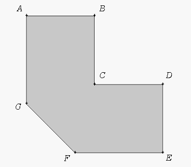
As an example of the general effects of vertex types on face meshes, consider the planar face shown in Figure 107: Seven-sided Planar Face. The following two examples illustrate the effects of different vertex type specifications applied to vertices C, F, and G on the shape of the resulting mesh.
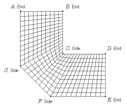
In Figure 108: Example Face Mesh—Side Inside Corner Vertex, vertices C, F, and G are specified as Side vertices. Therefore, the Meshing application treats sides BCD and EFGA as if each were a single edge. As a result, the entire face represents a mappable region, and the Meshing application creates a single checkerboard pattern for the mesh.
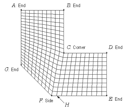
In Figure 109: Example Face Mesh—Corner Inside Corner Vertex, vertices C, F, and G are specified as Corner, Side, and End type vertices, respectively. As a result, the face is submappable, and the Meshing application creates two separate checkerboard patterns for the mesh. The upper-left submapped region is defined by the polygon ABCHFG. The lower-right submapped region is defined by CDEH. For both regions, the node at point H serves as an End type vertex for the purposes of mesh creation.


