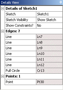
Details of Sketch
The first item under the Details of Sketch group, lists the sketch name in a value field that can be edited. This allows you to change the name of a sketch. All names and labels that you create must be unique, start with a letter, and contain only letters, digits and underscores. Spaces and hyphens are not recognized. If your supplied name does not end in a numeric and is not unique, a numeric will be added at the end. For example, MyPlane becomes MyPlane2, and MySketch5 becomes MySketch6.
The second item in this group is the Sketch Visibility property. Here you can set the sketch to:
Always Show Sketch: Makes the selected sketch always visible, even when viewing another plane.
Show Sketch: The sketch will be visible if the plane it belongs to is visible. This is the default visibility setting.
Hide Sketch: While hidden, it will only be displayed when it is selected in the Tree Outline, or is the active sketch while in sketching mode. While hidden, its edges will not be used for Auto Constraints or dimensions, unless it is the active sketch.
These correspond to the Sketch Visibility options available when you right click on a sketch in the tree.
The next item in this group is 'Show Constraints,' and its setting can be Yes or No. Changing this setting has a major effect on how the rest of the Sketch Detail View will look, as will be explained below.
Clicking the 'Details of' group selects the sketch and highlights all the edges in the sketch.
Dimensions: n
The 'Dimensions: n' group lists the dimension, where 'n' is the number of dimensions created with this active sketch. This group will not appear if there are no dimensions as part of the sketch. If there are dimensions, they will be listed item by item. Their appearance depends on whether or not they are Reference dimensions. If it is a dimension, its name is displayed enclosed in parenthesis in the title area, and its value is displayed in a read-only background value field. Otherwise, if the dimension is not a Reference dimension, then the title field is preceded with a check box (provided the model has been saved to a file and has a valid model name) which, once checked, will be marked with a "D" indicating that the dimension is driven by a Design Parameter. Once a dimension is driven by a Design Parameter, its value field becomes read-only.
If a dimension's value field is not read-only, then you can select it and change the value. The sketch(es) on this plane will then be updated to reflect this change. You can then click Generate to have this change reflected in your 3D model.
In general, you can select any dimension by selecting it in the Model View area, or by selecting it in the Details View. If you select the "Dimensions: n" group, all the dimensions in the sketch are selected and highlighted.
Edges: n
The "Edges: n" group, lists the edges contained in the sketch, where 'n' is the number of edges in the sketch. The format of this group is strongly affected by the setting of the "Show Constraints" switch above. If the switch is set to No, then each of the edges is listed as an element of this group, with its type as the title, and its value the name of the edge. If the switch is set to Yes, then each of the edges is listed as its own group, 'Edge Type Name,' containing a list with constraints that are applied to that edge.
If you select the "Edges: n" group, all of the edges are selected.
Edge Type Name
If the Show Constraints switch is set to Yes you will get one of these groups for each edge and construction point that has been created in this sketch. Edge types can be Line, Circle, Circular Arc, Ellipse, Elliptical Arc, Open Spline, Closed Spline, or Point. The items in this group (if any) are the constraints on the edge itself, and then any constraints on its start, end, or center point if they exist and have constraints. The constraint will be named and in the value field will be shown the other edge that is named in the constraint.
Selecting the group will select the edge.
Selecting one of the constraints actually selects the constraint, though these cannot be seen, and highlights the edges involved in the constraint. If you select one of the constraints, and then hit Delete, the constraint is deleted, not the highlighted edges.
Points: n
If the "Show Constraints" switch above is set toNo and you have created construction points while this sketch was active, these construction points are listed in the 'Points: n' group, where 'n' denotes their number. If the constraint switch is set to Yes then they are created as "Point Name" groups and appear identical to the "Edge Type Name" groups above.
References: n
The 'References: n' group lists points and edges in other sketches that are directly connected to points or edges in this sketch via constraints or dimensions. The origin point and axis lines for the plane are not listed here, but if you have more than one sketch in your plane and put a dimension between an edge in one sketch and an edge in another sketch, you will see this group show up.
You can select items in this group and they will be highlighted and selected. However, selecting the group itself has no effect.


