Sketch Projection allows you to project 3D model items onto a plane. You can select vertices, Point feature points, 3D edges, faces, and bodies to project. The result will be fixed edges in a special sketch that remain associative with the selected topology. So if the 3D model is updated, the associated sketch edges may change during a Generate. The edges in a sketch projection are fixed just like a plane boundary or sketch instance and cannot be moved, edited, or deleted by normal sketch operations. A Sketch Projection can be used just like normal sketches for creating other features. However, it cannot be used as a base sketch for Instances. Like Sketch Instance, because you are not allowed to make a sketch projection 'active' while in Sketching mode, they are not included in the drop down menu of sketches on the toolbar. Unlike other Sketch types, Sketch Projections can be suppressed like other features in the tree. Suppressed Sketch Projections will be treated as though "Hide Sketch" were in effect for them.
For faces, adjacent faces are treated as a group and projected as though they were a separate surface body. For bodies and face sets, the projection will be the outline of the body, as seen looking perpendicular (normal) from the plane. Interior edges, unless selected separately, will not be projected. While the DesignModeler application attempts to maintain associativity between the outline of the faces or bodies and sketch edges created, there are cases where this is not possible. If the topology of the projection changes so that the number of sketch edges resulting from an edge or face in the outline changes, it will not be possible to maintain proper associativity.
Also note that selected edges, faces, or face sets that are normal to the plane may not be projected. If a face or faces of a surface body or collection of adjacent faces would project as a line connected to an outline, then the projection will fail due to a non-manifold condition. See examples below. Also, note that since selected edges are processed individually, any edges that cannot be projected will be included in the problematic geometry display for the sketch. However, because adjacent face sets (or bodies) are processed as a single item, no single face can be identified as the cause of failure when a non-manifold condition occurs. For this reason, adjacent face set failures are not included in the problematic geometry. Single faces, which are not part of face sets, and are non-manifold, can be shown.
The basic steps to create a Sketch Projection are to first right click on the plane in the tree where you want to insert the Sketch Projection. Since a Sketch Projection must lie in a plane later in the tree than the 3D model items, the fixed planes do not have the option for creating a Sketch Projection. For other planes, Sketch Projection is an option in the Insert portion accessible via the right mouse button, but only if there are existing 3D model items created prior to that plane in the tree. Select the Geometry property in the Details View and then select the items to project.
Notations:
Selection — Generate is required to complete the Sketch Projection. Also, you should avoid selecting a combination of faces, edges, and/or bodies where they create duplicate or overlapping edges. For example if a single face is projected to a plane that is perpendicular to it, do not also select one of the edges which also end up being projected as a duplicate edge. Doing so creates duplicate or overlapping edges in the Sketch Projection which can cause problems for subsequent operations that use them. In fact, when projecting a face or body gives the same result as projecting just edges of that face or body, then you will be much better off selecting the edges to project. This is much, much faster, and is also more reliable in that it avoids the possibility of getting multiple edges from faces that are normal to the plane.
Tolerance Level — When selecting items to project, extremely tiny items may fall below a tolerance level and not be projected. This can occur if a tiny part (smaller than a few mm) is imported into a part with meter units. If there are edges on a face selected to project, such that the resulting edge would be extremely tiny, then it may not be present in the projection.
Projected Items — Normally, you will see the projected items displayed in black as they are "fixed" items that cannot be modified by you (other than modifying the items they are projected from). Sometimes, when edges are projected, separate edges that share the same 3D vertex may not project to the same 2D location if the vertex was created as a "tolerant" vertex is tolerant. In this case the Ansys DesignModeler application will create a coincident constraint between the resulting two curve endpoints and allow its constraint engine to try to force them together. When this occurs, the endpoints will show up as blue instead of black.
Tolerance Differences — In some cases due to tolerance differences or slight inaccuracies in the geometry, what appears as a closed profile from a sketch projection may have tiny gaps or overlaps. If you try to use a sketch projection for a feature, such as Extrude, and get a warning about the profile and the result is a surface body when you expected a solid, there is a workaround available to get around the tiny gaps or overlaps. Under the Concept Menu, create a Lines From Sketches, selecting the sketch created by the Sketch Projection. Then, instead of using the sketch created by the projection directly for the Extrude, use the created Line Body, and select the plane used by the projection to get the Direction Vector for Extrude. This will usually correct the problem.
Once you create a Sketch Projection in a plane, you cannot delete the base items as long as the Sketch Projection exists. In fact, just deleting the projection is not enough to allow the base items to be deleted. This is because you could still do an "Undo" to restore the projection. If you delete the plane that contains the projection, that will free up the dependence between the items and projection because the Undo and Redo stacks for that plane are cleared. Another way to clear the dependence is to Save via the File menu since that clears the Undo and Redo stacks for all planes.
Example 4: Projection of a single face
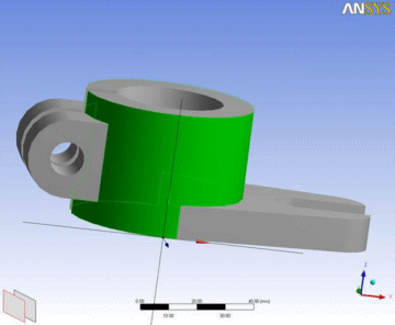
Here is a selected face and the plane to which it will be projected.
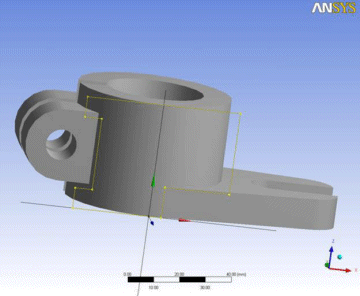
Here is its projection onto the plane.
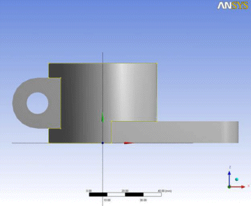
Looking straight at the plane, you can see that the projection created sketch edges from both edges of the face as well as a silhouette on the right of the cylindrical face.
Example 5: A Non-Manifold Body Projection Case
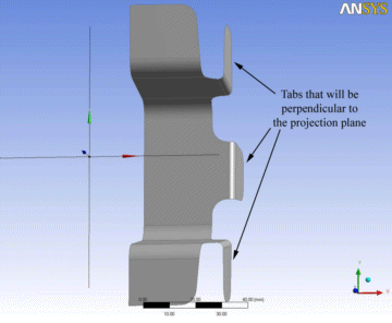
Here is a projection of a body, or all faces of a body that will cause a non-manifold error. While it has three tabs that are perpendicular to the plane, the one in the center does not cause a problem as it does not result in a line connecting to a region. However the other two tabs will cause a problem.
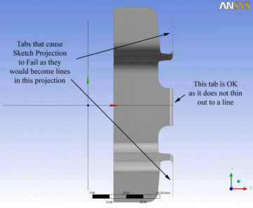
Here is the view looking directly at the plane. In this view it is obvious that two of the tabs result in single lines connecting to the rest of the region. This will result in an error and no projection will be created. To make this work, you could select all the faces of the body, and then unselect the faces of the two tabs that cause problems.


