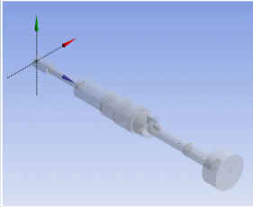
The Import Shaft Geometry feature uses a text file to generate a collection of line bodies with circular or circular tube cross sections. Each segment of the shaft is referred to as a station, and consists of a line body containing a single edge. Each line body’s cross section dimensions are defined in the text file. The line bodies themselves are arranged end to end starting from the origin of the selected base plane and extending out ward in its +Z direction. There is no limit to the number of stations the user may define in their text file so long as the bodies fit in the model bounding box and each station uses a unique identifier. The format of the text file is as follows:
Each line of the file defines a single station.
Each line contain four fields to define the station:
Station ID: must be a unique positive integer
Length: must be positive
Outer Diameter: The outer diameter of the cross section, which must be positive
Inner Diameter: The inner diameter of the cross section, which must be less than the outer diameter. This value may be zero is the cross section has no inner diameter.
A ‘#’ symbol indicates a comment. Any text that appears on a line after the ‘#’ symbol is ignored.
Several additional properties complete the definition of the Import Shaft Geometry feature:
Base Plane: The plane to use as the basis for the line bodies to be created from the text file. Bodies will be arranged starting at the base plane’s origin towards the +Z direction. When creating the Import Shaft Geometry feature, the current active plane will be chosen by default.
Model Units: Specifies the unit type of the text data to be imported. By default it is assumed to be the same units as the Ansys DesignModeler session.
Refresh: Set this property to Yes to force Ansys DesignModeler to refresh the Import Shaft Geometry feature by re-reading the source text file.
Example 1: Shaft text file
| Station ID | Length | Outer Diameter | Inner Diameter |
| 1 | 2.34 | 1.53 | 0 |
| 2 | 5.27 | 0.98 | 0 |
| 3 | 4.75 | 2.66 | 0 |
| 4 | 2.34 | 3.21 | 0 |
| 5 | 2.34 | 3.48 | 0 |
| 6 | 0.72 | 3.48 | 0 |
| 7 | 1.75 | 2.97 | 2.05 |
| 8 | 1.03 | 1.49 | 0.77 |
| 9 | 5.27 | 1.49 | 0 |
| 10 | 4.75 | 1.78 | 0 |
| 11 | 2.34 | 4.80 | 0 |
Produces the following geometry:

Other file management options:


