Example 11: Clip
This is an example of a simple clip used to keep snack bags closed, which uses the Edge Joints method to share topology. The file is available at:
Windows platform: ...\Program Files\ANSYS Inc\v242\AISOL\Samples\DesignModeler\clip
Linux platform: .../ansys_inc/v242/aisol/Samples/DesignModeler/clip
It is composed of three surface bodies: two plates on the top and bottom, and an elliptical spring between them. The top and bottom bodies touch each other, but should not share topology in the region so the clip can open. Shared topology is desired between the spring and the two plates.
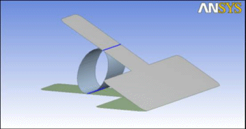
To join this model properly, a Joint feature is applied between the top plate and the spring. Then a second Joint feature is applied between the bottom plate and the spring. By performing two Joint operations, it prevents the top and bottom plates from being joined together. Note the blue edge joints displayed in the above picture. There are joints between the spring and plates, but not between the two plates themselves.
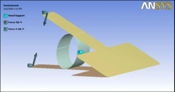
Once in the Mechanical application, forces are applied to the handle and a fixed support at the center of one side of the spring.
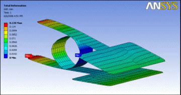
After solving, the result shows that the clip can be opened once adequate forces are applied to the handles. This type of model cannot be used with the Automatic shared topology method, since it would automatically create shared topology where the two plates of the clip touch.
Example 12: Crankshaft
In this example, a crankshaft is sliced to show how it can improve mesh quality by forming sweepable bodies. Since the model is composed of Solid bodies, the Automatic shared topology method is used. The file is available at:
Windows platform: ...\Program Files\ANSYS Inc\v242\AISOL\Samples\DesignModeler\crankshaft
Linux platform: .../ansys_inc/v242/aisol/Samples/DesignModeler/crankshaft
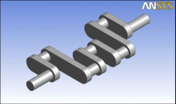
The initial model is one Solid body. It can be meshed, though it produces tetrahedral elements.
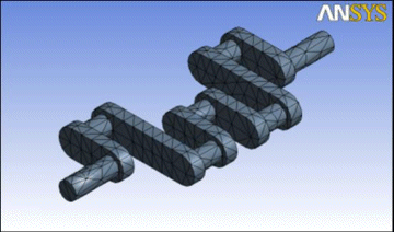
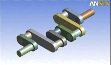
By slicing the model in the Ansys DesignModeler application, you can decompose it into pieces that can be swept meshed. After slicing, you must group the 13 resultant bodies into a multibody part.
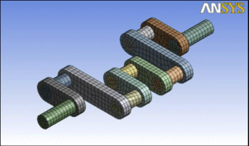
Then in the Mechanical application the model will be sweep meshable, which produces hex elements.
Example 13: Table (Correct)
This third example shows two ways of constructing a simple table model. In this first case, 3A, the table is built correctly, so that shared topology is achieved between Surface body edges and line body edges. The second case, 3B, shows how building the model incorrectly can cause topology not to be shared. The file for this example is available at:
Windows platform: ...\Program Files\ANSYS Inc\v242\AISOL\Samples\DesignModeler\table_correct
Linux platform: .../ansys_inc/v242/aisol/Samples/DesignModeler/table_correct
The model is composed of three bodies: two surface bodies which represent the table top, and a line body that represents the table’s frame. A fourth Solid body used to help build the model is suppressed. Note that since the multibody part contains a line body, only the Edge Joints method is used for sharing topology.
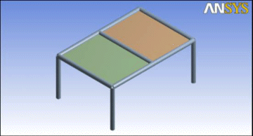
It is important to understand how to build the model so that edge joints are formed correctly. The most important steps of this model are the two Surfaces From Edges features, Surf1 and Surf2. In each of these two features, four line body edges have been selected. When the surface body is formed, four edge joints are automatically created to mark the coincidence of the surface body’s edges to their corresponding source edges from the line body. Remember that an edge joint tracks the relationship between a source model edge and a resultant model edge.
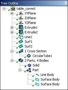
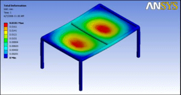
Once the three bodies are combined into a multibody part, the edge joints will cause the edges to combine into a single edge when the model is transferred out of the Ansys DesignModeler application to the Mechanical application. The analysis performed below shows that the table is in fact connected properly.
Example 14: Table (Incorrect)
This example shows the same table model from example 3A, but in this case, the model is built incorrectly. The file for this example is available at:
Windows platform: ...\Program Files\ANSYS Inc\v242\AISOL\Samples\DesignModeler\table_incorrect
Linux platform: .../ansys_inc/v242/aisol/Samples/DesignModeler/table_incorrect
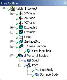
The model is composed of two bodies: one surface body which defines the table top, and a line body that represents the table’s frame. A third Solid body used to help build the model is suppressed. Note that since the multibody part contains a line body, only the Edge Joints method is used for sharing topology.
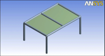
There is one fatal flaw in this model that causes topology not to be shared. The Surfaces From Sketches feature, SurfaceSk1, creates the surface body for the table top, but it does not create any edge joints. An edge joint is a relationship between a source model edge and a resultant model edge. Since the source edge in this case is from a sketch, no edge joint is created. Therefore, the surface body remains disconnected from the line body.
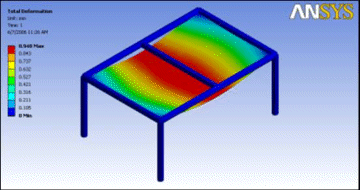
When the same loads are applied to this table model in the Mechanical application that were defined in example 3A above, the table top is in fact not connected to the frame, as shown below.
Example 15: Vise
In this example, a user wishes to establish better contact between the components of this vise model. For this case, the model consists of Solid bodies and the Imprints method will be applied. The file is available at:
Windows platform: ...\Program Files\ANSYS Inc\v242\AISOL\Samples\DesignModeler\vise.agdb
Linux platform: .../ansys_inc/v242/aisol/Samples/DesignModeler/vise.agdb
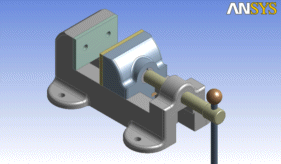
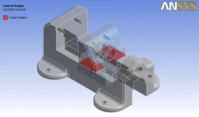
The model is a collection of 12 Solid bodies. If the bodies are kept separate, contact regions are detected upon transfer to the Mechanical application, though they do not necessarily match up well, as shown in this contact region between the base and sliding jaw.
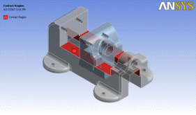
If you group the 12 bodies into a multibody part and apply the Imprint shared topology method, then the bodies are imprinted with each other during execution of the Share Topology feature. The following image shows the contact region between the base and sliding jaw in the Mechanical application using the Imprint shared topology method. Note how the faces identified in the contact regions exactly match the true contact between the bodies.
