


The types of bodies in a part often dictate which Shared Topology Methods can be applied. Ansys DesignModeler supports a variety of configurations that are useful in a number of analysis types, as described below:
Beam Structures
For analyses involving beams, the part consists of line bodies and optionally surface bodies. Edge joints are required for shared topology to take place. If you select None, the bodies are grouped in a multibody part but no sharing takes place.
Body Types: Line bodies only or line bodies with surface bodies
Shared Topology Method(s): Edge Joints, None
Shell Structures
For shell analysis, you group surface bodies together in the part. Usually Automatic shared topology is applied, which shares topology anywhere the surface bodies touch one another. The Edge Joints method is also applicable and offers finer control over which specific topologies are shared, but requires that the joints be defined before the Share Topology feature in the Tree Outline.
Body Types: Surface bodies only
Shared Topology Method(s): Automatic, Edge Joints, Imprints, None
Solid Structures
For solid analysis, you group solid bodies together in the part. Often bodies are grouped this way to accommodate slicing of the model to achieve a more desirable mesh, to separate regions for different material assignments, or in flow volume analysis involving enclosures where the solid and fluid regions are grouped together. Usually Automatic shared topology is applied.
Body Types: Solid bodies only
Shared Topology Method(s): Automatic, Imprints, None
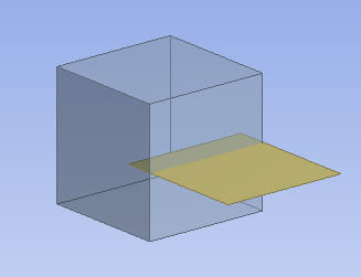
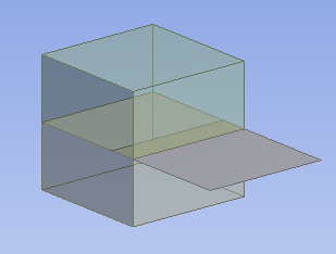
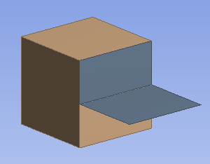
Solid/Shell Flow Volumes
In this configuration, you group solid bodies and surface bodies together in the part. The surface bodies are embedded inside the solids to segment the flow volume for fluid flow analysis. The surface bodies become walls inside the flow volume, and the surface bodies themselves are consumed by the Share Topology operation. Any portions of the surface bodies that are not contained by the solids are removed. Usually Automatic shared topology is applied. For this setting, it is advised to set the Share Topology feature's Allow Solid/Shell Parts property to No to prevent any portions of surface bodies that may lie outside of the solid volumes from being kept. Otherwise, a body that is intended to serve as a wall in a fluid flow analysis may inadvertently be treated as an external shell.
Body Types: Solid and surface bodies
Shared Topology Method(s): Automatic, Imprints, None
Solid/Shell Surface Coatings
In this type of analysis, surface bodies that are coincident to the faces of solid bodies are defined, and the surface bodies and solid bodies are grouped into the same part. The surface bodies merge with the faces of the solid bodies, but transfer downstream with the surface bodies intact to simulate coatings. Usually Automatic shared topology is applied.
Body Types: Solid and surface bodies
Shared Topology Method(s): Automatic, Imprints, None
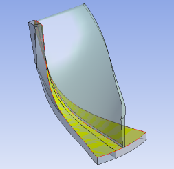
Solid/Shell Structures
In this configuration, you group solid bodies and surface bodies together in the part. The surface bodies are joined with the solids to support structural analysis. Usually Automatic shared topology is applied. For this setting, it is advised to set the Share Topology feature's Allow Solid/Shell Parts property to Yes to ensure the surface bodies external to the solid volumes are kept intact. Otherwise, the model may be treated as a flow volume.
You can set up solid/shell structures in several ways. Outlined below are three ways to create such a configuration:
Embedded surface:

The surface body is partially embedded into the solid. When meshed, the nodes of the surface that are inside the solid will be conformal with the solid mesh.
Embedded surface with slicing:
The surface body is partially embedded into the solid, although the solid itself is sliced where the surface embeds into it. When meshed, the nodes of the surface that are inside the solid will be conformal with the solid mesh. What makes this method different from the embedded surface method described above is that the embedded surface with slicing method may allow for a hexahedral mesh.
Surface coating anchor:
The surface body is attached to the solid by a surface coating.
Body Types: Solid and surface bodies
Shared Topology Method(s): Automatic, Imprints, None
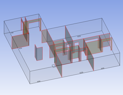
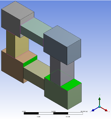
Consider the example below.
Example 10: Shared Topology Method
In this example, the Shared Topology Method property is set to:
Automatic for top level part,
Imprint for bottom center body,
None for bottom right body, and
Default for all other bodies.
In the image below, the edge coloring shows the connectivity information. The bodies set to Default or Automatic took part in Automatic and Imprint Shared Topology. The body with Imprint as the Shared Topology took part in only Imprint. The body with None did not take part in any Shared Topology.
Note that some features applied after Shared Topology can create new bodies, for example Slice. In these cases if a user changes the shared topology type on a body that was created after Shared Topology, then DesignModeler will disregard the change.
For more information, see Shared Topology Examples of a clip, crankshaft, table, and vise.
Also see Shared Topology Limitations.