


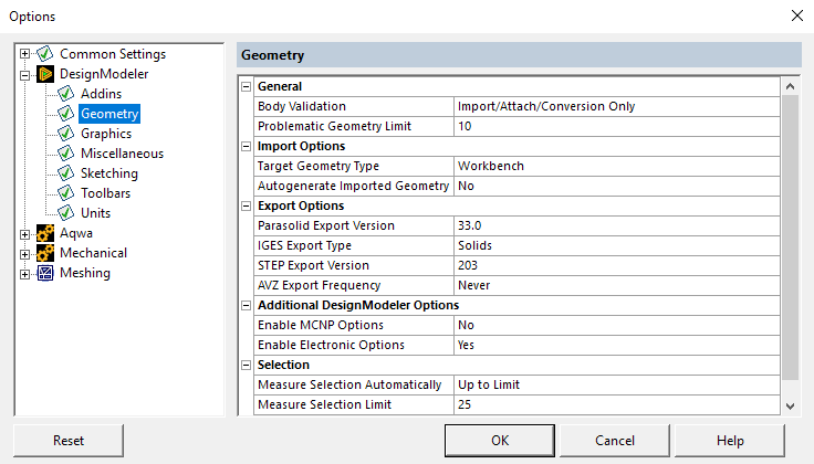
Geometry options include:
General
The General category includes:
Body Validation: The Body Validation allows you to select one of three values:
Always: All bodies created by features are validated.
Import/Attach/Conversion Only: Only bodies created from Import and Attach features and those that are converted to DesignModeler type by any feature are validated (default).
Never: No bodies are validated. Note that when this option is chosen, all Import and Attach features will produce a warning that informs you bodies have not been validated.
By enabling Body Validation, DesignModeler will perform a number of checks on the model to ensure its correctness. By setting the option to Always, the checking will be performed for every feature. The checking process can be time consuming for large models, so it is recommended to perform to validation only for imported geometry. There are cases where performing local operations may result in an invalid model that DesignModeler does not detect. For example, if a blend operation is performed on a corner such that the blended face intersects faces on the opposite side of the model, DesignModeler will not detect the error unless Body Validation is enabled for all features.
The highlighted Blend face above has a radius so large that it cuts through the inner faces of the hollow box. DesignModeler will detect this type of error only if Body Validation is enabled for all features.
Problematic Geometry Limit: This defines the maximum number of problematic geometries collected for a feature. The selectable range of the Problematic Geometry Limit is from 1 to 20, with 10 being the default.
Import Options
The Import Options category includes:
Target Geometry Type: This preference tells what the Target Geometry should be when creating an Attach feature. It can be a Workbench or DesignModeler type. The default is Workbench type.
Auto-generate Imported Geometry: The default is No.
Yes: allows automatic generation of the model that is imported using File-> Import External Geometry File and File->Attach to Active CAD Geometry.
No: you have to explicitly generate the model to complete Import or Attach feature.
Export Options
The Export Options category includes:
Parasolid Export Version: The DesignModeler application writes your model in Parasolid format when you Export using the .x_t or .x_b extension. This preference enables you to set which Parasolid version the model is written to, which is useful when you want to transfer your model into a third-party CAD program that uses a different Parasolid version.
IGES Export Type: Allows you to export solids or trimmed surfaces when exporting a model to an IGES file. The default is Solids.
STEP Export Version: On Windows, two versions of the neutral file format are supported:
AP203 (default)
AP214
Additional DesignModeler Options
The Additional DesignModeler Options category includes:
Enable MCNP Options: The default is No. Use to enable several features specific to MCNP operations:
Bodies will be renamed in DesignModeler when exporting to an MCNP file.
During MCNP export, Named Selections will be created for geometries that are invalid with respect to the MCNP format.
Material properties will be available for bodies created by a Primitive feature.
A warning will be generated for errors during MCNP export.
Enable Electronic Options: The default is Yes. Select No to deactivate the DesignModeler Electronics Menu in the Tools Menu.
Selection
The Selection category includes:
Measure Selection Automatically: allows you to select one of three settings:
Always
Never
Up to Limit, in which case the limit is given in the next preference (default).
Measure Selection Limit (#faces/edges): specifying the maximum number of 3D (model) edges or faces to trigger automatic selection measurements. The default is 25.
Measurement Accuracy: specifies accuracy used to compute Volume, Area, and/or length of selected items. Three settings are offered:
High, gives better accuracy, but can take 10-25% longer
Normal (default), this is the default which gives good accuracy and reasonable time
Low, gives slightly lowered accuracy, but can be 10-25% faster
The default setting for the Measure Selection preferences is Up to Limit, and Limit = 25. They occur in two instances:
The Surface Area and Volume properties under the Detail View of a body
The (current) Selection Information area at the lower-right side of the screen (that is, towards the right, on the status bar).
Selection measurements may be a CPU-intensive endeavor; especially (1) when selecting complex bodies (that is, solids or surfaces) in the Tree View, and/or (2) when accumulating large and complex (model) face/edge selection sets, most probably via the Extend Selection toolbar buttons. The mentioned option settings allow you to influence DesignModeler behavior.
If automatic selection measurements are disabled - either due to the option setting Never or because of going "over" the specified Limit, then DesignModeler will skip the measurements. However, there will be a right mouse button Context Menu option Measure Selection, which will allow you to compute the measurements on demand.