BladeGen provides a variety of tools to assist the user in evaluating the design of the blade system. These tools are described in the following sections:
The Output | Check Output menu command performs various check on the model that are too time consuming to be done every time the geometry is updated. These checks highlight problems and suggest methods of improving the design. It is recommended that these checks be performed before outputting geometry.
The Auxiliary View can display a variety of data sets describing the blade design. An Auxiliary View is always displayed in the upper right hand corner of the BladeGen main window and its content is controlled by the toolbar to the right. Additional, separate Auxiliary Views can be opened as needed, with each displaying its own set of data.
The Auxiliary Views are described in detail in Auxiliary View Details .
The throat lengths can be displayed in the Blade-to-Blade View by selecting Show Throat(s) in the popup menu. The throat length for a single blade system is simply the minimum distance between adjacent blades. When splitters are added, there is more than one possible throat location. When the Show Throat(s) option is activated, BladeGen will display all possible throat curves for the active layer in the Blade-to-Blade view, along with a color coded legend showing the lengths of those curves.
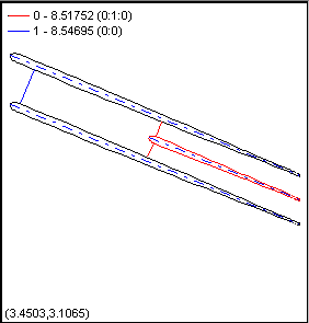
In the example shown above, two throat lengths are shown. The first throat is throat number 0, which has a total length of 8.51752 units, and consists of two parts: one connecting blade 0 to blade 1, and one connecting blade 1 to blade 0. The second throat is throat number 1, which has a length of 8.54695 units, and which is measured between blade 0 and blade 0.
The throat curves on each layer at a given location in the flow path can be assembled into surfaces. The throat area is the total area of these surfaces for all throats between all blades in the machine. Throat surfaces can be displayed in the 3D view by selecting the "Throat Surfaces" option in the Display Group Control Dialog. This dialog is accessed using the Display Group Control... command in the 3D view’s popup menu. To see the surface area as a number, select Analyze | Surface Areas. For details, see Surface Areas.
Surface areas for the throat(s) and blade(s) can be displayed using the Model | Analyze | Surface Areas... menu command or the ![]() toolbar button. This will display a dialog box, as shown below. The areas are calculated by breaking up the surface into rectangular regions indicated by the Integration Parameters controls. The Surface of Interest can be one of the following: Throat Surface Area, Corrected Throat Area, or Blade Surface Area. These are described below.
toolbar button. This will display a dialog box, as shown below. The areas are calculated by breaking up the surface into rectangular regions indicated by the Integration Parameters controls. The Surface of Interest can be one of the following: Throat Surface Area, Corrected Throat Area, or Blade Surface Area. These are described below.
|
Surface of Interest |
Description |
|---|---|
|
Throat Surface Area |
The Throat Surface Area is the area of the throat surface, as displayed in the 3D View. |
|
Corrected Throat Area |
The Corrected Throat Area multiplies the area by the dot product of the local surface normal and the assumed flow direction (see "whiskers" in 3D View). This attempts to correct for situations where the throat surface is angled to the flow and, therefore, does not represent the actual throat area. |
|
Blade Surface Area |
The Blade Surface Area is the area of the blade surfaces (sides only, not ends). |
The areas reported in the Surface Area Dialog are total areas for all throats between all blades in the machine.
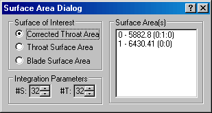
In the example shown above, two throat areas are shown. This case is taken from the example in Throat Area and Length . The first area is area number 0, which is 5882.8 square units, and consists of two parts: one between blade 0 and blade 1, and one between blade 1 and blade 0. The second area is area number 1, which is 6430.41 square units, and which is between blade 0 and blade 0.
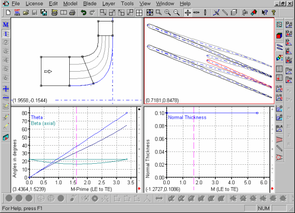
The File | Compare... menu command can be used to compare the current blade design against an existing BladeGen file. The selected file is displayed in gray behind the current design, as shown below.
The comparison is displayed in the Meridional, Angle, Thickness, Prs/Sct, Blade-to-Blade, and Graph Views. In the Graph View, the user must select the Show Comparison Curves popup menu command to enable the display. The 3D and Contour Views do not display comparisons.
Select the File | Compare... menu command again to turn off the comparison.